Figure 5, Figure 4, 1 - spd – Advanced Protection SPDee User Manual
Page 3
SPD
ee
is a Type 1 SPD. SPD
ee
is suitable for
use almost anywhere (not as a plug-in SPD).
Type 1 SPDs are evaluated more rigorously by
UL 1449 for NEC
®
Article 285 compliance. Type
1 SPDs and their connecting leads have been
evaluated for line side applications without need
for supplemental overcurrent protection. Type 1
SPDs include internal overcurrent protection. As
a generalization, there are practical maintenance
reasons for installing on the load side of the main
overcurrent device (i.e. Type 2 installation). When
connected on load side of main disconnect, we
recommend connecting via a 30A circuit breaker
due to 10 AWG conductors. The circuit breaker
serves as a disconnect switch and provides NEC
®
imposed short circuit protection to the conductors
in Type 2 or 4 applications. (cUL units are Type 2
due to different cUL criteria.)
Simplified Explanation of Operation: SPDs sense
overvoltage and create a momentary short circuit
to redirect harmful surge energy to earth ground.
They reset automatically and wait for the next surge.
This is similar to the pressure relief valve on a water
heater: pressure goes up, valve opens to relieve
pressure and then resets. In an electrical system, an
SPD senses overvoltage, shorts temporarily sending
energy to ground and then resets. SPDs are capable
of repeating this function thousands of times.
Parts List
1 - SPD
ee
suppressor including 3’ (~1m) conductors
1 - 3/4” conduit nut
1 - L bracket mounting kit; includes two panhead
screws
1 - Data Sheet
1 - Installation Sheet (this document)
Most SPD
ees
have demonstrated 200kA &
100kA Short Circuit Current Ratings (SCCR)
including leads. See UL Label markings on SPD
or see Data Sheet for specs.) Supplemental
overcurrent protection is not required to protect
this SPD. However, NEC
®
convention requires
that connecting conductors have overcurrent
protection in Type 2 or 4 applications. Follow
applicable codes.
This device features internal overcurrent and
overtemperature protection that will disconnect
effected surge suppression components at the end
of their useful life, but will maintain power to the load
– now unprotected. If this situation is undesirable
for the application, follow these instructions for
replacing the device. SPD
ee
is ultrasonically welded
closed and contains no user serviceable parts.
Specifications
Temperature Operating
-40
o
C (-40
o
F) to 60
o
C (+140
o
F)
Temperature Storage
-55
o
C (-67
o
F) to 65
o
C (+149
o
F)
Wire Size & Installation Torque 10 AWG; 18 inch-pounds
Appropriate Circuit Breaker
based on conductor size
30A (SPD includes internal OCP)
NEMA 250 Enclosure Rating
Type 4X with appropriate
sealing & sealing condulets
Voltage rating & Application
Before installing SPD, verify by nameplate voltage
or model number that it has the same voltage rating
as the power distribution system. See attached Data
Sheet or call APT Tech Support at (800) 237-4567 as
appropriate. The SPD’s specifier or user should be
familiar with the configuration and arrangement of
the power distribution system. The system is defined
by how the secondary windings of the transformer
supplying the service entrance main or load are
configured. This includes whether or not the transformer
windings are referenced to earth via a grounding
conductor. The system configuration is not based on
how any specific load or equipment is connected to a
particular power distribution system. SPDs should be
installed per the distribution system, not per a load or
motor’s wiring connection.
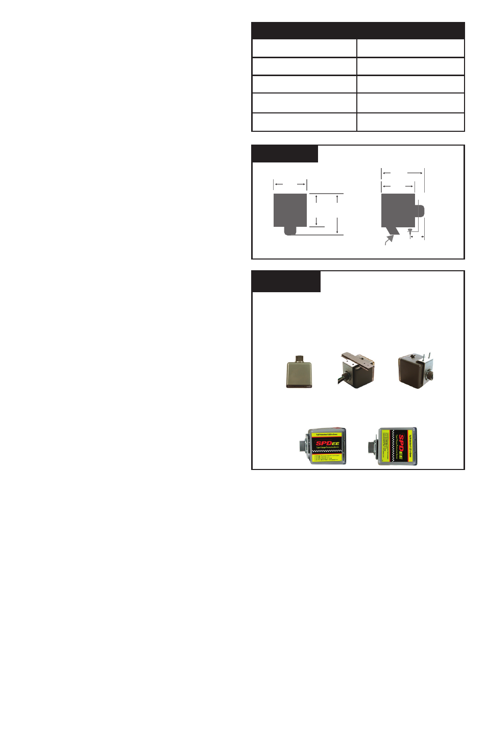
Bracket Mount
for flat surfaces
Std. 3/4”-14 Nipple
DIN-Rail Mount
(rail not incl.)
Supplemental Product Label may be affixed if standard
top label is not viewable
• 3/4” pipe nipple (conduit nut included)
• With L-bracket mounting kit accessory
- Standard 35mm DIN-Rail (not included)
L-bracket tightens onto DIN-Rail
- Standard flat mounting surface
Attach L-bracket to surface via mounting holes
Figure 5
SPD
ee
MOUNTING OPTIONS
3.26”
3.26”
1.15”
4.13”
3/4”-14
Sized for std 35mm DIN-Rail
3.31” 3.57”
Weight: 1.60 lbs
(0.73 kg)
Figure 4
DIMENSIONS & WEIGHT
3