Warning, Installation, Not good good – Advanced Protection SPDee User Manual
Page 2: Figure 3, Figure 2
2
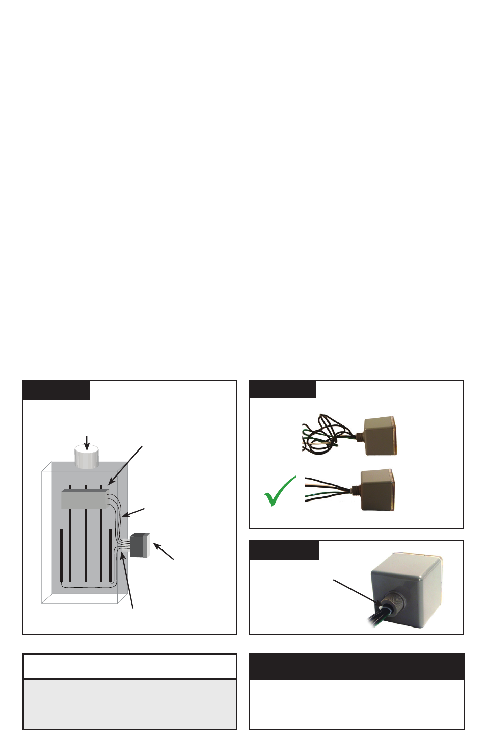
LEADS SHOrT & STrAIGHT
X
NOT
GOOD
GOOD
Cut off
Excess Length
Do Not Loop
or Coil
Short
& Straight
Figure 2
A
B
C
G
N
BREAKER
(Type 1 or individual equipment installations may vary)
▪
Use closest
breaker to SPD
▪
Locate SPD close
to intended breaker
▪
Keep Leads Short
as Possible
▪
Avoid Sharp Bends
▪
Rotate SPD
ee
such
that LED indicator
is most visible
▪
Outdoor installation requires appropriate weather
sealing at nipple (gasket, sealing conduit, etc.)
To Protected Loads
Figure 1
Sealing gasket:
two choices
1.) At 3/4" nom.
thread: ID is 1.05"
2.) At 0.14" high 'base
step': ID is 1.25"
Figure 3
INSTALLATION
Pre-Plan your installation. You need to accomplish the following:
▪
Meet all National and Local codes (NEC
®
Article 285 and UL 1449 address SPDs).
▪
Confirm System voltage to SPD voltage (120V SPD will fail instantly on 240V, 277V, etc.).
▪
Mount SPD as close to panel or equipment as possible to keep leads short.
(long leads hurt performance substantially).
▪
Ensure leads are as short and straight as possible, including neutral and ground. If using a
breaker, use a breaker position that is close to the SPD and the panel’s neutral & ground.
▪
If using a breaker, recommended breaker size is 30A due to 10 AWG conductor.
▪
Make sure system is grounded per NEC
®
and clear of faults before energizing SPD.
(inadvertent system problem may fail SPD).
▪
Never Hi-Pot test Any SPD. (will prematurely fail SPD).
1. Use voltmeter to check voltages and ensure correct SPD. See Data Sheet for specs and wire-outs.
2. Determine Mounting method (See Figure 5) – weather resistant equipment may be required.
3. If SPD has optional Dry Contact, pre-plan its installation.
4. Remove power from panel/source. Confirm panel/source is deenergized.
5. Identify breaker location and SPD location. Position SPD such that LED is best visible.
6. Mount SPD – weather resistant applications require additional sealing, o-rings, etc. (not included)
- Remove an appropriately sized knockout from panel.
- Connect conductors as appropriate – short and straight as possible (Hi-Legs are Phase B).
7. Label or mark conductors as appropriate (neutral: white, ground: green, energized: black, hi-leg: orange).
8. Make sure system is bonded per NEC
®
and is clear of hazards or faults before energizing.
(N-G bonding not per NEC
®
will fail SPDs: #1 cause of SPD failures)
9. Energize and confirm proper operation of green LED indicator and/or options.
(Affix supplemental label accessory if appropriate. See Figure 5.)
V
WARNING
▪
Confirm XO N-G Bonding at Upstream Transformer
▪
Do Not Hi-Pot Test
▪
Resulting Damage is not Covered Under Warranty
VERIFY THAT ALL POWER CIRCUITS ARE
DEENERGIZED BEFORE MAKING CONNECTIONS
All electrical connections should be performed by a qualified
(licensed) electrician or technician. All wiring must comply with
the National Electrical Code (NEC
®
) and applicable local codes.
TYPICAL PANEL
INSTALLATION
V
WARNING