Bryant 502A User Manual
Page 7
—
7
—
SERVICE
IMPORTANT: If repairs to refrigerant cycle components (e.g.,
compressor, filter drier, etc.) are required, recover all refrig-
erant from the system by using both high-pressure and low-
pressure ports, then remove base unit from the space.
I. COMPONENT LOCATION AND ACCESS
Refer to Fig. 2 for component locations and access panel loca-
tions. If a suspended ceiling has been installed beneath the
unit, the hinged access panels may not open fully. Remove
the panels at the hinged sides to provide full access.
II. FILTERS
Filters are cleanable and should be inspected and cleaned at
regular intervals monthly or as conditions require. Filters
can be washed with water or vacuumed as needed. They are
located in front of the evaporator coil and may be removed by
sliding them horizontally out to edge of unit. See Fig. 1 and
2. No tools are required for installation or removal of filters.
III. CONDENSER COIL
The condenser coil is accessible through the bottom access
door marked condenser section, or through side access panel
on condenser section, or through side access panel on con-
denser section. Use a stiff brush when cleaning coil. Be care-
ful not to bend aluminum fins.
Connect the condenser washdown pan drain connection
(
3
/
4
-in. FPT) to the building drain using a
3
/
4
-in. MPT hose.
Entering through unit bottom condenser access door, use a
water hose or other suitable equipment to flush out dirt and
wash down coil. Be careful not to force water spillage out of
condenser washdown pan.
IV. EVAPORATOR COIL
The evaporator coil is accessible for cleaning through the
bottom access door marked “Evaporator Section.” When nec-
essary, wash coil with a commercial cleaner (Oakite 164) or
dishwasher detergent using a pressurized spray canister.
Flush coil from return-air duct side and take care not to get
water in ductwork or unit insulation.
V. CONDENSATE DRAIN
Clean and empty drain pan at least once a year to prevent
sludge build-up.
VI. LUBRICATION
Lubrication of the condenser and evaporator motors is not
necessary since both are equipped with permanently lubri-
cated bearings. Do not oil.
VII. MOTOR SPEED ADJUSTMENT
Direct-drive evaporator motors require no adjustment.
VIII. CONDENSER MOTOR
All 502A036-060 units contain belt-driven adjustable-pulley
condenser fan systems. All 502A048 unit fan motors are
shipped with adjustable pulley 2 turns open and 502A060
units are shipped at 5 turns open, and can be adjusted to
increase fan speed. The 502A036 unit fan motors are shipped
with adjustable pulley at 4 turns open.
IX. BLOWER WHEEL SERVICING
In-space servicing is recommended for the evaporator and
condenser blowers. Both are removed by loosening and
removing the 4 screws that hold them in place. In both cases,
the entire assembly is then moved outside of the base unit.
Once outside, the blower wheel and condenser shaft bearings
and/or evaporator motor can be serviced.
X. BELT-DRIVE FAN ADJUSTMENTS
Follow these instructions for adjusting motor pulley pitch
setting (to change fan speed), for aligning motor shafts and
pulleys, and for adjusting belt tension on all belt-drive fan
systems.
To change the fan speed:
1. Shut off unit power supply, tag disconnect(s).
2. Loosen belt by loosening fan motor mounting bolts.
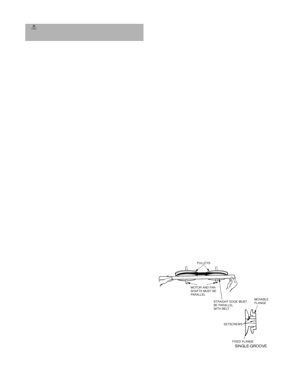
3. Loose movable flange setscrew (see Fig. 4).
4. Screw movable flange toward fixed flange to increase
speed and away from fixed flange to decrease speed.
Increasing fan speed increases load on fan motor. Do
not exceed maximum speed specified in Table 1.
Observe maximum evaporator flow rate limits per
note on Table 4.
5. Set movable flange at nearest keyway of pulley hub
and tighten setscrew.
6. Tighten fan motor mounting bolts.
To align fan and motor shafts, loosen motor from mounting
and reposition as necessary. To align fan and motor pulleys,
loosen fan pulley setscrews on fan shaft and slide fan pulley
along shaft until straightedge check confirms alignment (see
Fig. 4). Tighten setscrews. Check all motor mounting bolts.
To adjust belt tension:
1. Loosen fan motor mounting bolts.
2. Slide motor away from fan shaft for proper belt ten-
sion (
1
/
2
-in. deflection with 8 to 10 lb of force) and
tighten motor mounting bolts.
XI. BLOWER BELT ADJUSTMENT
Inspect blower belt for wear, proper belt tension, and pulley
alignment as conditions require or at the beginning of each
heating and air conditioning season. Refer to Step 8 — Fan
Speed on page 5 for adjustment and alignment procedures.
XII. CONTROL BOX SIDE ACCESS PANEL
The control box side access panel is held in place with
1
/
4
-in.
self-retaining fasteners. When these fasteners are pulled,
the access panel can be turned around 180 degrees so that its
metal lip will line up with the metal lip on bottom of unit.
This enables the access panel cover to hang down, exposing
the base unit wiring diagram and enabling the service per-
son to work more freely.
WARNING: Electrical shock can cause personal
injury. Open all remote disconnects and tag before ser-
vicing this equipment.
Fig. 4 — Evaporator-Fan Pulley Adjustment