Table 5 — condenser-fan performance – Bryant 502A User Manual
Page 6
—
6
—
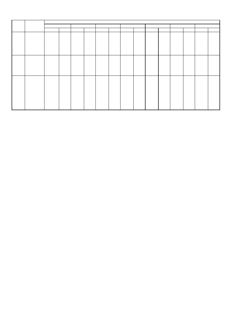
Table 5 — Condenser-Fan Performance
LEGEND
kW — Total Fan Motor Power Input (kilowatts)
NOTES:
1. Above fan performance is based upon coil and deducted casing losses only.
2. External static pressure (ESP) is measured in inches water gage (in. wg).
3. Interpolation is permissible. Do not extrapolate.
4. Minimum one turn open of motor pulley is required on unit sizes 036 and 060.
5. Number of turns open applies to field setting of motor pulley.
6. Factory setting as follows: 036, 4 turns open; 048, 2 turns open; 060, 5 turns
open.
START-UP
I. UNIT PREPARATION
Make sure unit has been installed in accordance with instal-
lation instructions and applicable codes.
II. COMPRESSOR MOUNTING
Compressors are internally spring mounted. Do not loosen or
remove compressor holddown bolts.
III. INTERNAL WIRING
Check all electrical connections in unit control boxes and
tighten as required. Be sure wires are not in contact with
sharp edges or refrigerant tubing.
IV. REFRIGERANT SERVICE VALVES
Each unit system has 3 Schrader-type service ports, one on
the suction line, one on the compressor discharge line, and
one for low-ambient damper kit. Be sure that caps on the
ports are tight. One Schrader-type valve is located under
both the high-pressure switch and low-pressure switch.
V. COMPRESSOR ROTATION
It is important to be certain compressor is rotating in the
proper direction. To determine whether or not compressor is
rotating in the proper direction:
1. Connect service gages to suction and discharge pres-
sure fittings.
2. Energize the compressor.
3. The suction pressure should drop and the discharge
pressure should rise, as is normal on any start-up.
If the suction pressure does not drop and the discharge pres-
sure does not rise to normal levels:
1. Note that the condenser fan may also be rotating in
the wrong direction.
2. Turn off power to the unit and tag disconnect.
3. Reverse any two of the unit power leads.
4. Reapply power to the unit; remove tag. Energize
compressor.
5. Verify correct refrigerant pressures.
The suction and discharge pressure levels should move to
their normal start-up levels.
NOTE: When the compressor is rotating in the wrong direc-
tion, the unit will sound louder than normal and will not
provide cooling.
VI. FAN ROTATION
Check fan rotation to ensure progression in proper direction.
VII. COOLING
To start unit, turn on main power supply. Set system selector
switch at COOL position and fan switch at AUTO. position.
Adjust thermostat to a setting below room temperature.
Compressor, condenser and evaporator motors start on clo-
sure of contactors.
A. To Shut Off Unit
Set system selector switch at OFF position or reset thermo-
stat at a position above room temperature. Units are
equipped with Cycle-LOC™ protective device.
Cycle-LOC™ device prevents an automatic restart of a unit’s
compressor that has been shut down due to a safety device
trip. The Cycle-LOC device may cause an indicator light on
the thermostat subbase to illuminate upon a safety trip (if
the thermostat includes this feature).
Be sure to check reason for safety trip before resetting the
Cycle-LOC device. Compressor restart is accomplished by
manual reset at the thermostat by first turning the selector
switch to OFF and then back to ON position.
UNIT
502A
AIRFLOW
(cfm)
EXTERNAL STATIC PRESSURE (in. wg)
0.0
0.1
0.2
0.3
0.4
0.5
0.6
Turns
kW
Turns
kW
Turns
kW
Turns
kW
Turns
kW
Turns
kW
Turns
kW
036
1650
2
.84
—
—
—
—
—
—
—
—
—
—
—
—
1600
—
—
2
.82
—
—
—
—
—
—
—
—
—
—
1550
—
—
—
—
2
.80
—
—
—
—
—
—
—
—
1500
3
.72
—
—
—
—
2
.78
1
.84
—
—
—
—
1450
4
.63
3
.70
—
—
—
—
2
.76
1
.83
—
—
1400
—
—
4
.61
3
.68
—
—
—
—
—
—
1
.81
1350
5
.51
—
—
—
—
3
.67
—
—
2
.73
—
—
1300
—
—
5
.50
4
.57
—
—
3
.65
—
—
2
.71
048
2700
2
.90
—
—
—
—
—
—
—
—
—
—
—
—
2600
—
—
2
.87
—
—
—
—
—
—
—
—
—
—
2550
3
.81
—
—
—
—
—
—
—
—
—
—
—
—
2450
—
—
3
.77
2
.83
1
.89
—
—
—
—
—
—
2350
—
—
—
—
—
—
2
.80
1
.86
—
—
—
—
2300
4
.68
—
—
3
.74
—
—
—
—
0
.90
—
—
2200
—
—
4
.66
—
—
—
—
2
.77
1
.82
0
.86
060
3100
3
1.34
—
—
—
—
—
—
—
—
—
—
—
—
3000
—
—
3
1.32
—
—
—
—
—
—
—
—
—
—
2900
—
—
—
—
—
—
2
1.39
—
—
—
—
—
—
2850
4
1.11
—
—
3
1.24
—
—
—
—
—
—
—
—
2750
—
—
4
1.07
—
—
—
—
2
1.32
—
—
—
—
2700
—
—
—
—
—
—
3
1.17
—
—
—
—
—
—
2650
—
—
—
—
—
—
—
—
—
—
—
—
1
1.37
2600
5
.95
—
—
4
1.01
—
—
—
—
2
1.26
—
—
2550
—
—
—
—
—
—
—
—
3
1.12
—
—
—
—
2500
—
—
5
.92
—
—
—
—
—
—
—
—
—
—
2450
—
—
—
—
—
—
4
.97
—
—
—
—
2
1.21
2400
—
—
—
—
5
.90
—
—
—
—
3
1.08
—
—