Bryant 502A User Manual
Page 5
—
5
—
6. Unsweat the cut portions of the refrigerant piping in
evaporator section at the closest bell joint. The bell
joints are used to connect field-supplied refrigerant
piping to evaporator section. Cut and braze a length
of tubing to extend refrigerant piping outside the
evaporator section.
7. Cut condenser-fan motor wiring at the partitions sep-
arating condenser and evaporator sections.
8. In the condenser section, install a junction box adja-
cent to the D-shaped grommet.
9. Install evaporator and condensing sections in desired
locations. Refer to Steps 10-12 below.
10. Use appropriate length of no. 16 American Wire Gage
(AWG) (minimum),
4
/
64
-in. insulated copper wire to
reconnect cut condenser-fan motor wires. Make con-
nections in junction boxes installed in earlier steps.
Follow all applicable electrical codes.
11. Use sufficient length of refrigerant piping to recon-
nect piping cut in previous step. Liquid line tubing is
3
/
8
-in. OD copper tubing, and hot gas line is
1
/
2
-in. OD
copper tubing.
12. Replace top panels on each section.
13. Evacuate refrigerant system to 500 microns.
14. Recharge unit with R-22 refrigerant following
Charging Charts (page 8) in these instructions. Use
refrigerant charge as indicated on unit.
NOTE: National Electric Code (NEC) disconnects are
required at each section if units are not installed within line
of sight of each other.
After splitting sections, additional refrigerant must be added
to system to ensure proper refrigerant charge. The amount of
refrigerant to be added depends on length of tubing added to
system and operating temperatures of system. Allow unit to
operate at least 10 minutes before adjusting refrigerant
charge.
Since standard roomtop unit has negligible line losses, split-
ting the system can increase line loss and decrease system
capacity.
IX. FIELD CONTROL WIRING
Install a Bryant-approved thermostat assembly accessory
according to installation instructions provided by thermostat
manufacturer. Locate thermostat assembly on a solid wall in
the conditioned space away from drafts to sense average
room temperature.
Using thermostat cable or equivalent single leads of no. 18
AWG colored wire, route cable or wire from the subbase ter-
minals, up and through connector on unit side (below power
lead junction box) and connect to low-voltage terminal block
inside the control box.
X. THERMOSTAT WIRE
Use 18 gage for 0 to 50 ft long wires and 16 gage for 51 to
75-ft wire lengths.
XI. STEP 8 — FAN SPEED
Adjust condenser fan speed and evaporator fan speed to meet
job requirements. Enter the condenser and evaporator sec-
tions through the hinged access panels on the bottom of
units (see Fig. 2). See Service section of this document for
general service procedures.
A. Evaporator-Fan Motors
Standard evaporator fans are direct-driven designs. Size 036
units have single-speed motors and require no adjustment.
Sizes 048 and 060 units use two-speed fan motors. Refer to
Table 3 for standard evaporator fan performance. The evapo-
rator fan motor factory speed selection is shown on the label
diagram affixed to base unit. If other than factory speed set-
ting is desired, refer to label diagram for motor reconnection.
Optional evaporator fan drives (for unit sizes 048 and 060)
are belt-drive designs. Refer to Table 4 for optional evapora-
tor fan performance. Adjust the motor pulley setting as
required to provide the project design evaporator airflow
rate. Pulley setting must limit the airflow rate to maximum
of 2250 cfm.
See Service section for instructions on checking motor shaft
and fan shaft alignment, pulley alignment and belt tension.
B. Condenser-Fan Motors
Condenser-fan motors are belt driven. Fan speed must be
adjusted to maintain condenser airflow at the flow rate
specified in Table 1. Refer to Table 5 for condenser fan per-
formance data. See Note 6 for factory drive pulley settings.
Adjust the motor pulley setting as required to provide design
condenser airflow through the site’s condenser duct system.
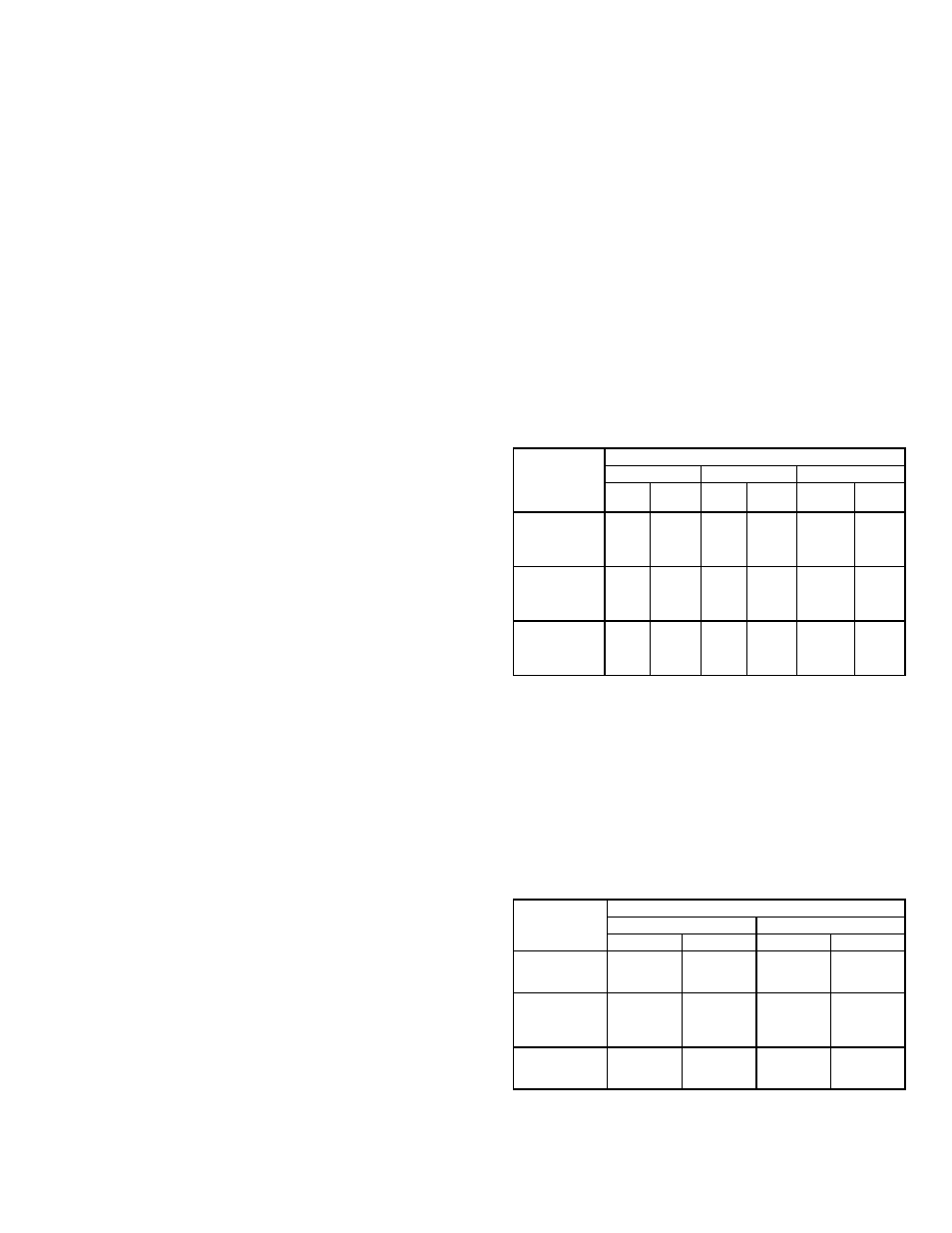
Table 3 — Evaporator-Fan Performance
LEGEND
*Standard direct drive indoor-fan motor (IFM). For optional belt drive
IFM performance, see following table.
NOTES:
1. Above fan performance is based on wet coil and deducted casing
losses, and clean factory-installed permanent cleanable filter.
2. Evaporator fans are direct drive (except sizes 048, 060 indoor-fan
motor option).
3. Interpolation is permissible, do not extrapolate.
Table 4 — Optional Belt-Drive
Evaporator-Fan Performance
NOTE: Pulley setting must be adjusted to limit cfm to 2250 cfm
maximum. Unit operation beyond that limit may result in blow-off and
condensate problems.
AIRFLOW
(cfm)
UNIT SIZE — 502A
036
048*
060*
ESP
Fan
kW
ESP
Fan
kW
ESP
Fan
kW
900
.69
.44
—
—
—
—
1000
.57
.46
—
—
—
—
1100
.42
.49
1.10
.45
1.11
.52
1200
.23
.52
1.01
.49
1.045
.55
1300
—
—
.90
.51
.97
.57
1400
—
—
.79
.55
.88
.59
1500
—
—
.67
.58
.78
.62
1600
—
—
.54
.61
.67
.64
1700
—
—
.39
.64
.53
.67
1800
—
—
.22
.67
.52
.70
1900
—
—
.03
.70
.40
.74
2000
—
—
—
—
.28
.78
ESP — External Static Pressure (in. wg)
kW
— Total Fan Motor Power Input (kilowatts)
AIRFLOW
(cfm)
UNIT SIZE — 502A
048
060
ESP
Fan kW
ESP
Fan kW
1800
—
—
—
—
1850
—
—
—
—
1900
—
—
—
—
1950
.81
1.03
—
—
2000
.72
1.05
—
—
2050
.63
1.07
—
—
2100
.55
1.08
1.02
1.17
2150
.47
1.11
.93
1.21
2200
.42
1.14
.84
1.24
2250
.34
1.17
.75
1.27