Inspect/prepare installation site, General information, General specifi cation – Beckett FII 85 User Manual
Page 5: Table 1 – burner specifi cations, Notice special requirements, Clearances to burner and appliance
RWB 6104 BAFII R01
Page 5
General Specifi cation
Table 1 – Burner Specifi cations
Capacity
‘HLX’ Heads
Firing rate: - 0.40 – 1.50 GPH
Input: Min./Max - 56,000 /210,000 Btu/h
‘FBX’ Heads
Firing rate: - 0.40 – 1.35 GPH
Input: Min./Max. - 56,000/189,000 Btu/h
Certifi cation/
Approvals
UL certifi ed to comply with ANSI/UL296 &
tested to CSA B140.0
Fuels
U. S No. 1 or No. 2 heating oil only (ASTM
D396)
Canada No. 1 stove oil or No. 2 furnace oil
only
Electrical
Power supply - 120 volts AC, 60 Hz, single
phase
Operating load - 5.8 Amps max
Motor - 1/7 hp, 3450 rpm, NEMA 48M
frame PSC rotation CCW when
facing shaft end
Ignition - Continuous duty solid-state igniter
Fuel pump
Outlet pressure - Note 1
Air tube
ATC code - See Table 2
Dimensions
(with cover)
Height (maximum) - 13 inches
Width (maximum) - 14 inches
Depth - 6-11/16 inches
Air tube diameter - 3-1/2 inches
*
Note 1. See appliance manufacturer’s burner specifi cations for
recommended outlet pressure.
•
Notice Special Requirements
For recommended installation practice in Canada,
refer to the latest version of CSA Standard B139 &
B140.
Concealed damage — If you discover damage to
the burner or controls during unpacking, notify the
carrier at once and fi le the appropriate claim.
When contacting Beckett for service information —
Please record the burner serial number (and have
available when calling or writing). You will fi nd the
serial number on the silver label located on the left
rear of the burner. Refer to Figure 1.
Inspect/Prepare Installation Site
Clearances to Burner and Appliance
Provide space around burner and appliance for
ease of service and maintenance. Check the mini-
mum clearances against those shown by the ap-
pliance manufacturer and by applicable building
codes.
•
•
General Information
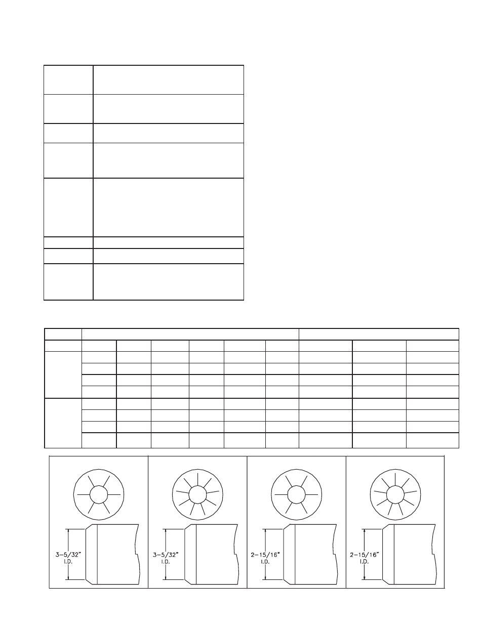
Table 2 – Air Tube Combinations (ATC) & Dimensions
ATC codes for usable air tube lengths dim. “A” (Figure 3)
Firing rate range (gph)Min-Max
3”
5”
7”
9”
ATC Code
Head
AFII 85
AFII 100
AFII 150
Adjustable
w/stop
screw Head
Design
HLX30
HLX50
HLX70
HLX90
HB
AF2-6
0.4-0.85 gph
0.65-1.00 gph
0.75-1.35 gph
HLX30
HLX50
HLX70
HLX90
HC
AF2-9
N/A
0.65-1.00 gph
0.75-1.50 gph
HLX30
HLX50
HLX70
HLX90
HD
AF2-6
0.40-0.85 gph
0.65-1.00 gph
0.75-1.10 gph
HLX30
HLX50
HLX70
HLX90
HE
AF2-9
N/A
0.65-1.00 gph
0.75-1.35 gph
Head Design
- Fixed
FBX30
FBX50
FBX70
FBX90
HFXS
FB0
0.40-0.65 gph
0.55-0.75 gph
0.75-1.00 gph
FBX30
FBX50
FBX70
FBX90
HGXS
FB3
0.55-0.85 gph
0.55-1.10 gph
0.85-1.20 gph
FBX30
FBX50
FBX70
FBX90
HHXS
FB4
N/A
0.75-1.10 gph
1.10-1.25 gph
FBX30
FBX50
FBX70
FBX90
HIXS
FB6
N/A
0.85-1.15 gph
1.15-1.35 gph
HB 6 slot
HC 9 slot
HD 6 slot
HE 9 slot