Replacement parts diagram – Beckett FII 85 User Manual
Page 15
RWB 6104 BAFII R01
Page 15
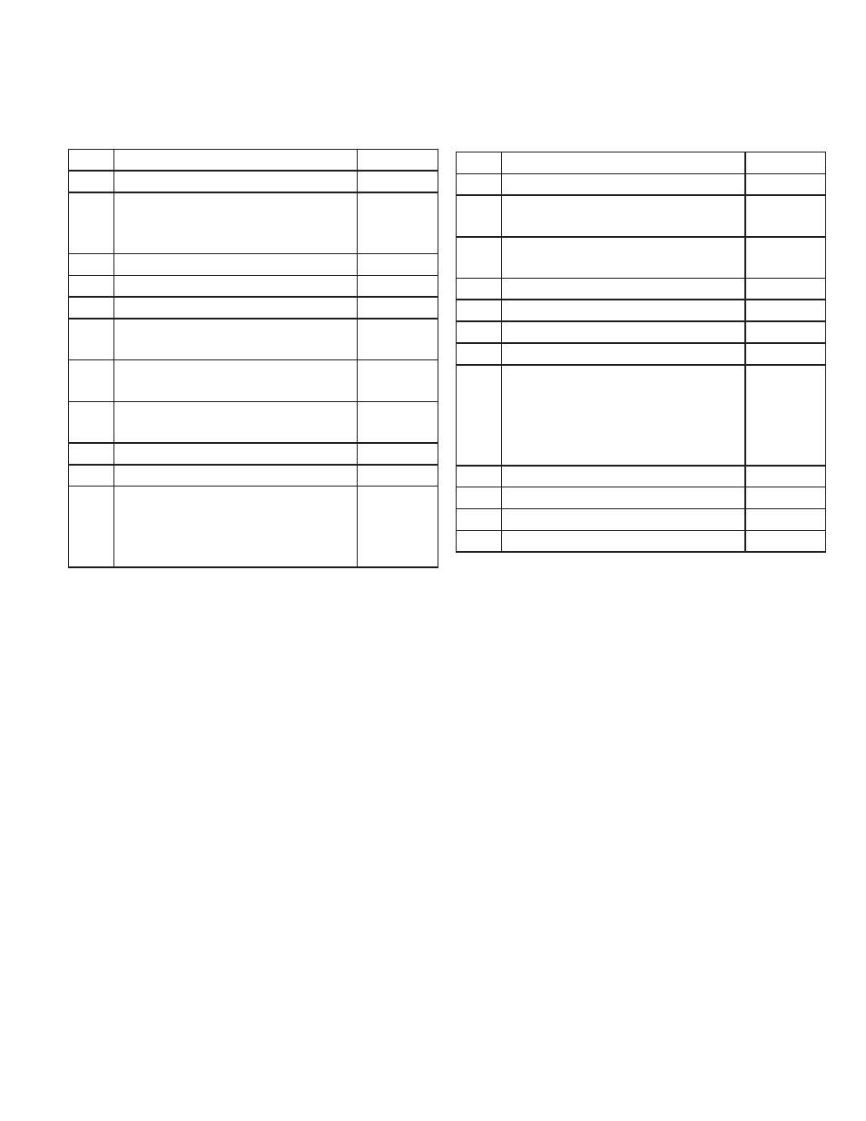
Item
Description
Kit No.
1
Air tube combination
Specify
2
Blower Wheel: AFII 85 (4-1/4”)
AFII 100 (4-1/2”)
AFII 150 (4-1/2”)
21439U
21438U
21438U
3
Electrical box
30613BK
4
Connector tube, 8” Copper
5394U
5
Coupling, Motor to Pump
21437U
6
Electrodes: HLX Heads
FBX Heads
51484U
51670U
7
Escutcheon Plate: AFII Blank
AFII 140psi
31623
3162302
8
Flange Kit, (adjust. 3-1/2” ID w/gas-
ket)
51480
9
Fuel Pump: Cleancut
2184404U
10
Gasket, fl ange
31658
11
Head: FBX:FB0, FB3, FB4, or FB6
HLX: AF2 6 Slot Head
AF2 9 Slot Head
Head insulator Kit (FB0, 3, 4, 6 only)
Specify
51671U
51672U
51685
Item
Description
Kit No.
12
Igniter, Electronic
51805U
13
Inlet air scoop, plastic, sound insu-
lated
51485
14
Housing ass’y: AFII 85 & 100
AFII 150
51584U
51476U
15
Motor: 1/7 hp, 3450 rpm, 115V/60Hz
21444U
16
Nozzle adapter
213
17
Nozzle Line Electrode Head ass’y
Specify
18
Pedestal Kit, AFII Mounting
51481
19
Primary control
R7184A Interrupted ignition
R7184B Valve-on Delay
R7184P Valve-on/Motor-off Delay
R7184P With Alarm Contacts
7455U
7456U
7457U
7458U
20
Rear Access Door
51424U
21
Stop Screw, Replacement kit
51483
22
Splined Nut
3666
23
Dial, Air Adjustment (UL approved)
187
Replacement Parts List
Replacement Parts Diagram