Briggs & Stratton 01814-0 User Manual
Page 8
8
Briggs & Stratton Power Products Automatic Transfer Switch
Installation and Operator’s Manual
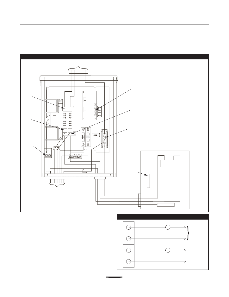
Figure 3 — A Typical Installation Diagram for Transfer Switch
Main
Main Distribution Panel
Ground Bus
Neutral
Bus
To Generator
Neutral
Terminal
To Utility Power
Supervisory
Contacts
Load
Connection
Ground Lug
Generator
Connection
Utility
Connection
1.
Terminals on control module are for installer supplied
contactors to lock out large loads. Example: air
conditioner, electric hot water heater, etc.. Contacts
are connected in series with the contactor control
circuit (Figure 4).
2.
Tighten all wire connections/fasteners to proper
torque. See inside transfer switch enclosure for proper
torque values.
Figure 4 — Terminals on Control Module
Air Conditioner Contactor
Supply
Contactor
Neutral
120 VAC