13fitting the upper door, 14fitting the upper soft stop mechanism, 15aligning the doors – Liebherr CBNPes 3967 PremiumPlus BioFresh NoFrost User Manual
Page 11: Putting into operation
u
On the upper door, rotate the turn hinge
Fig. 20 (23)
outwards, parallel to the edge of the door.
Fig. 21
NOTICE
Cables may be twisted and damaged as a result!
u
Use the template.
u
Detach the supplied template
Fig. 21 (61)
from the turn
hinge and use it to prevent the turn hinge
Fig. 21 (23)
and
bush from turning.
u
Using a screwdriver, push out the turn
hinge
Fig. 20 (23)
from underneath and
remove it from the door, complete with
cable.
u
Using a screwdriver, push out the stopper
Fig. 20 (62)
from underneath and transfer it
to the opposite side.
u
Thread in the cable of the turn hinge
Fig. 20 (23)
on the
opposite side and insert the turn hinge.
u
Detach the template
Fig. 20 (61)
and secure it in the turn
hinge.
u
Plug in the connector
Fig. 20 (60)
.
u
Lay the cable in the guide.
Appliances without soft stop mechanism:
u
Snap the cover
Fig. 20 (63)
into place on the door.
4.3.13 Fitting the upper door
u
Place the upper door on the middle bearing pin
Fig. 13 (41)
,
close the door and attach the upper turn hinge
Fig. 10 (23)
so that it engages in the upper side of the appliance.
u
Screw theturn hinge
Fig. 10 (23)
firmly into place (with
4 Nm). Possibly make preliminary holes with a bradawl or
use a cordless screwdriver.
u
Snap cover
Fig. 10 (20)
and cover
Fig. 10 (21)
into place.
u
Plug in the connector
Fig. 8 (12)
again.
u
Lay the cable in the guide.
u
Attach the cover
Fig. 8 (10)
again.
Appliances without soft stop mechanism:
u
Turn the cover
Fig. 9 (6)
through 180°, attach it from the
outside to the handle side and snap it into place.
u
Turn the cover
Fig. 9 (11)
through 180°, attach it from the
outside to the handle side and snap it into place.
Appliances with soft stop mechanism:
u
Leave the door open.
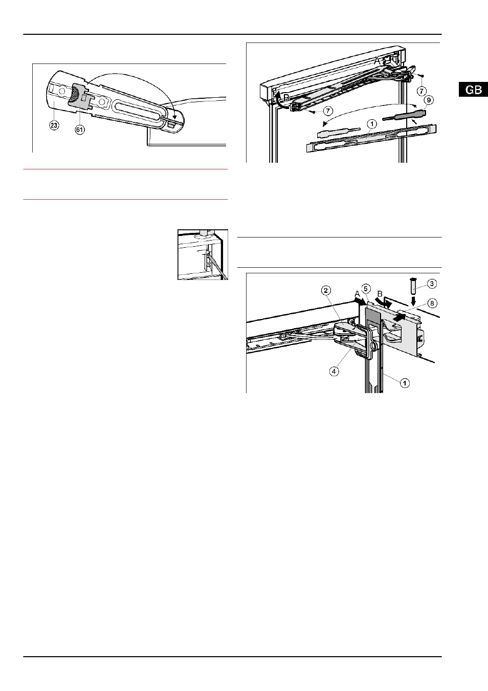
4.3.14 Fitting the upper soft stop mechanism*
For appliances with soft stop mechanism.
For appliances without soft stop mechanism proceed with
Fig. 22
u
Remove the cover
Fig. 22 (9)
from the faceplate
Fig. 22 (1)
and re-insert it at the other side.
u
Engage the upper soft stop unit with the joint on the hinge
side (A) and swivel into place (B).
w
The screw holes at the left and right have to register.
u
Screw the soft stop unit firmly into place. (2x Torx® 15)
Fig. 22 (7)
Note
u
Keep to the correct order. First attach the panel over the soft
stop bracket, then the cover.
Fig. 23
u
Attach the faceplate
Fig. 23 (1)
to the soft stop bracket
Fig. 23 (4)
so that the catches face inwards and the front
faces the appliance.
u
Slide on the cover
Fig. 23 (5)
from the outside (A) and swivel
it over the bearing element
Fig. 23 (8)
(B).
u
Attach the cover
Fig. 23 (5)
and engage it as far as the first
detent.
w
The openings for the pin are on top of one another after the
soft stop bracket has been positioned.
u
Draw the soft stop bracket
Fig. 23 (4)
to the bearing element
Fig. 23 (8)
and insert the pin
Fig. 23 (4)
from above so that
the square is seated in the depression.
u
Now completely snap the cover
Fig. 23 (5)
onto the bearing
element
Fig. 23 (8)
.
w
Pay attention that the cover fits properly so that the door
closes properly and the pin is secured.
u
Twist the safety lock
Fig. 23 (2)
for removal.
u
Snap thefaceplate
Fig. 23 (1)
onto the door.
u
Turn the cover
Fig. 6 (6)
through 180°, attach and engage it
on the handle side.
4.3.15 Aligning the doors
u
Possibly align the door to the appliance housing by way of
the two slots in the lower turn hinge
Fig. 15 (55)
and middle
turn hinge
Fig. 13 (42)
. To do so, unscrew the middle screw
in the bottom turn hinge
Fig. 15 (55)
.
Putting into operation
* Depending on model and options
11