9transferring the handles, 10fitting the lower door, 11fitting the lower soft stop mechanism – Liebherr CBNPes 3967 PremiumPlus BioFresh NoFrost User Manual
Page 10: 12transferring the cable connection (upper door), Putting into operation
u
Unscrew
Fig. 15 (56)
the turn hinge
Fig. 15 (55)
.
u
Unscrew the bearing element
Fig. 15 (58)
, turn it through
180° and screw it firmly into place again inside.
u
Carefully lift off the cover on the handle side
Fig. 15 (57)
and
transfer it to the opposite side.
u
Screw the bottom turn hinge
Fig. 15 (55)
firmly into place
(with 4 Nm) on the new hinge side, possibly using a cord-
less screwdriver.
u
Re-insert the stopper
Fig. 15 (51)
into the other hole.
u
Re-insert the bearing pin
Fig. 15 (52)
together with the
washer and adjustable-height foot. In so doing, pay attention
that the locating lug points backwards
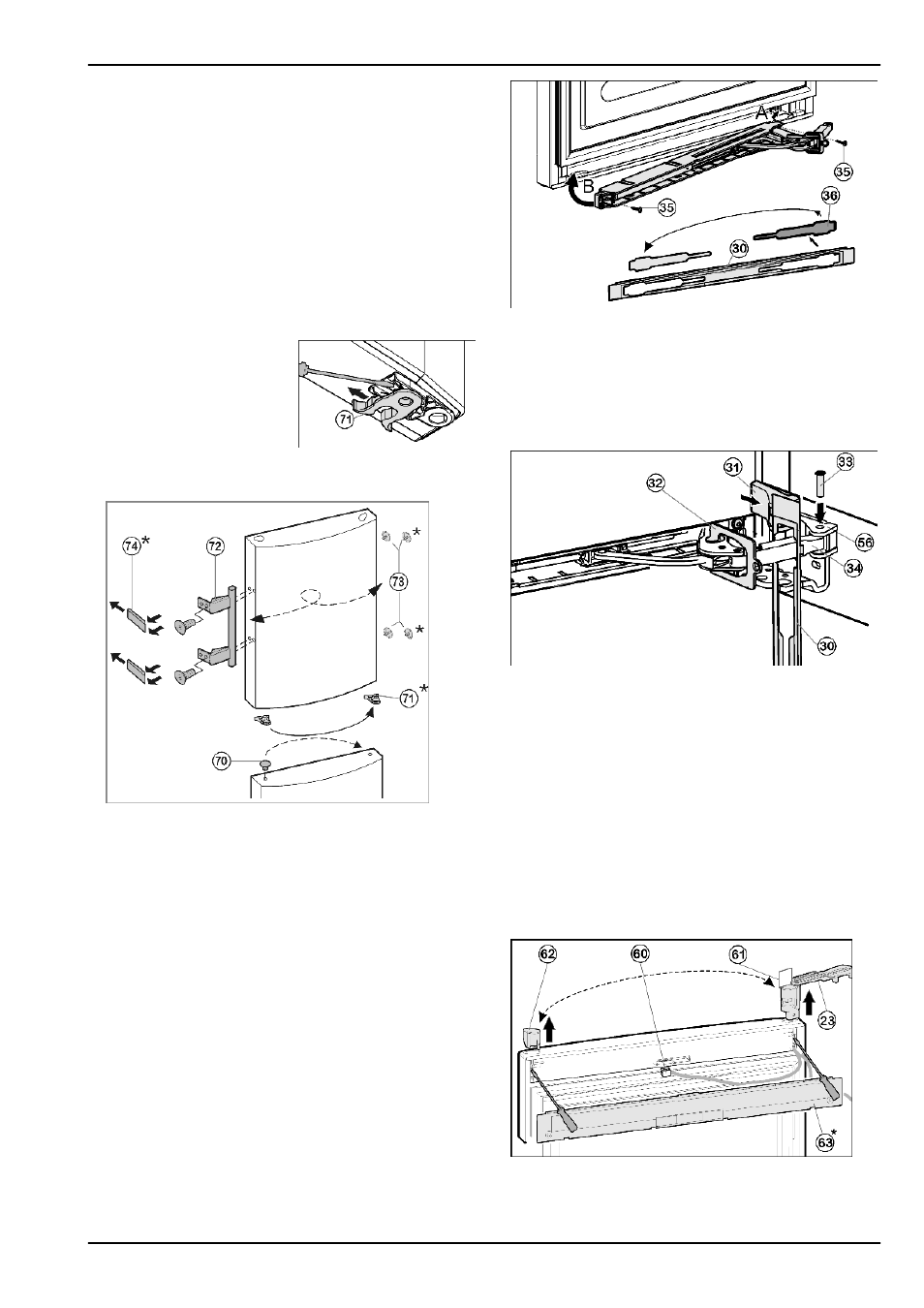
4.3.9 Transferring the handles
For appliances without soft stop mechanism (on both
doors):
u
Transfer the spring clamp
Fig. 16 (71)
: Depress the
latch nose and pull the
spring clamp off over it.
u
Slide the spring clamp into
place on the new hinge
side until it clicks into
place.
Fig. 16
For all appliances:
Fig. 17
u
On the bottom door: Lift the stopper
Fig. 17 (70)
out of the
door bearing bush and transfer it.
u
On both doors: Detach door handle
Fig. 17 (72)
, stopper
Fig. 17 (73)
and pressure plates
Fig. 17 (74)
and transfer to
the opposite side.
u
When fitting the pressure plates on the opposite side, make
sure they snap properly into place.*
4.3.10 Fitting the lower door
u
Place the door from above onto the bearing pin
Fig. 15 (52)
.
u
Close the door.
u
Place the plastic cap
Fig. 13 (40)
back on the middle turn
hinge
Fig. 13 (42)
u
Pass the middle bearing pin
Fig. 13 (41)
through the middle
turn hinge
Fig. 13 (42)
into the lower door.
Appliances with soft stop mechanism:
u
Attach the washer
Fig. 13 (44)
to the middle bearing pin
Fig. 13 (41)
.
4.3.11 Fitting the lower soft stop mechanism*
For appliances with soft stop mechanism.
For appliances without soft stop mechanism proceed with
Fig. 18
u
Remove the cover
Fig. 18 (36)
from the faceplate
Fig. 18 (30)
and re-insert it at the other side.
u
Engage the joint of the soft stop unit on the hinge side (A)
and swing it into place (B).
w
The screw holes at the left and right have to register.
u
Screw the soft stop unit firmly into place(2x Torx® 15)
Fig. 18 (35)
.
Fig. 19
u
Attach the faceplate
Fig. 19 (30)
to the soft stop bracket so
that the catches face forwards and the front faces the appli-
ance.
u
Draw the soft stop bracket
Fig. 19 (34)
to the bearing
element
Fig. 19 (56)
and insert the pin
Fig. 19 (33)
from
above so that the square is seated in the depression.
u
Attach and engage the cover
Fig. 19 (31)
.
w
Pay attention that the cover fits properly so that the door
closes properly and the pin is secured.
u
Twist the safety lock
Fig. 19 (32)
for removal.
u
Snap thefaceplate
Fig. 19 (30)
onto the door.
u
Close the lower door.
4.3.12 Transferring the cable connection
(upper door)
Fig. 20
u
Using a screwdriver, disengage the cover
Fig. 20 (63)
from
the door.
u
Detach the connector
Fig. 20 (60)
.
Putting into operation
10
* Depending on model and options