Block diagram – Behringer MX882 User Manual
Page 11
11
ULTRALINK PRO MX882
5. BLOCK DIAGRAM
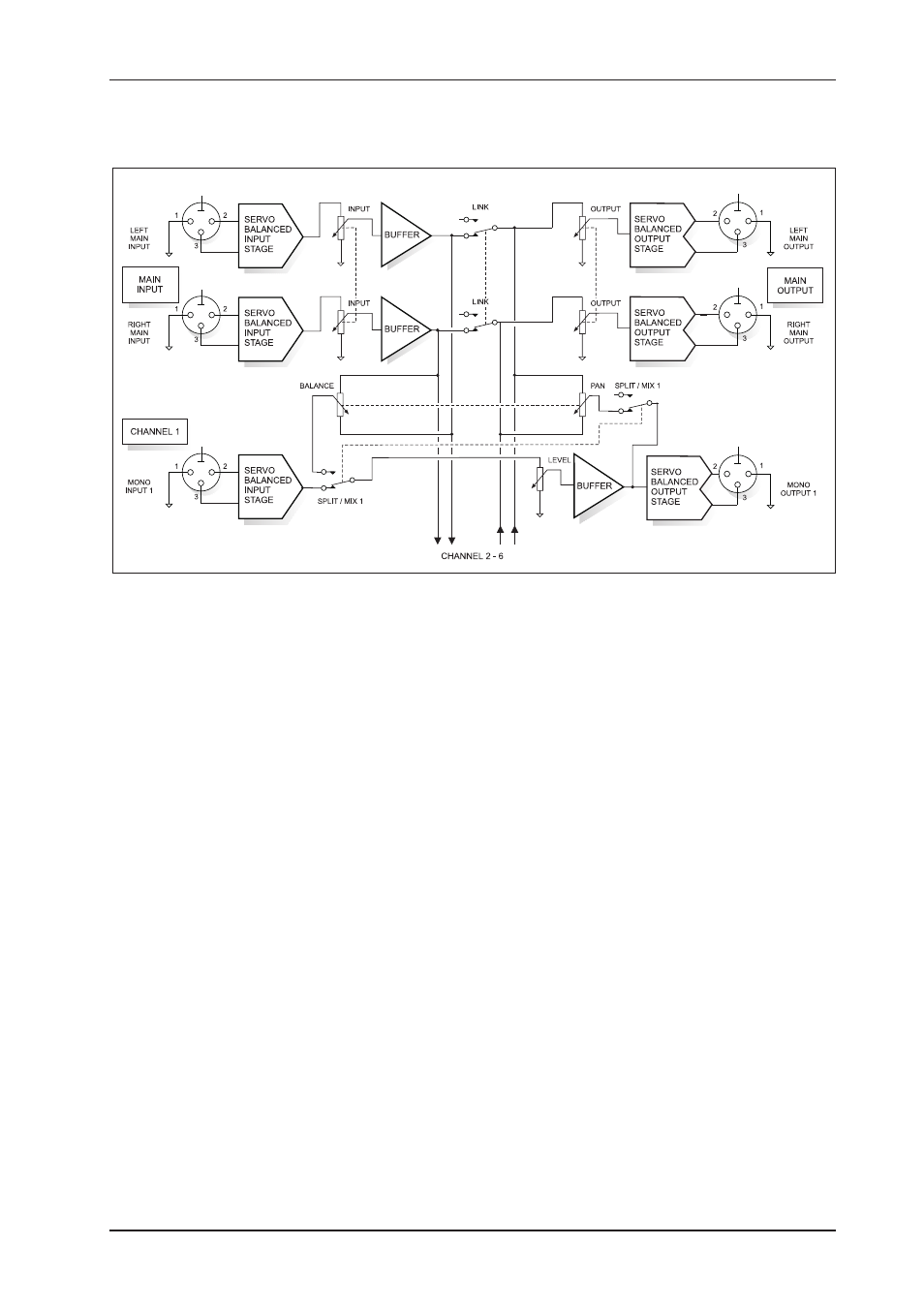
Fig. 5.1: Block diagram of the BEHRINGER ULTRALINK PRO MX882
MAIN Section
Both main inputs interface via the MAIN INPUT LEVEL control with the input bus as well as with the main
outputs. The MAIN OUTPUT LEVEL control determines the output level of the signals which are summed by
the second bus (i.e., the output bus) and are subsequently routed to the main outputs.
SPLIT Mode
In SPLIT mode, the main input signal is sent via the BALANCE control to the output buffer amplifiers of the
mono channels, with the LEVEL control determining the output level of the respective channel. The maximum
gain is +15 dB.
MIX Mode
In MIX mode, the input signals of the mono channels are collected via the LEVEL and PAN controls and are
routed to the output bus. In this mode, the LEVEL control determines the amount of each channel at the output
bus, while the PAN control is responsible for the allocation of the input signal to the left and right main outputs.
Additionally, the input signal is routed to the respective mono outputs, i.e., the circuit acts as a matching
amplifier. The LEVEL control allows for level compensation of up to +15 dB.
5. BLOCK DIAGRAM