Specifications – Bryant 4-Way Multipoise Induced Combustion Gas 311AAV User Manual
Page 4
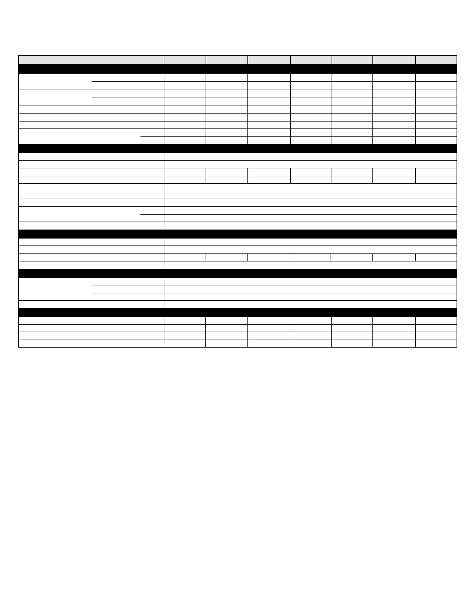
SPECIFICATIONS
UNIT SIZE
RATINGS AND PERFORMANCE
Input Btuh*
Output Capacity (Btuh)
Nonweatherized ICS
AFUE
Nonweatherized ICS
Certified Temperature Rise Range
o
F
Certified External Static Pressure
Heat/Cool
Heating
Cooling
ELECTRICAL
Unit Volts-Hertz-Phase
115-60-1
Operating Voltage Range
Min-Max
104-127
Maximum Unit Amps
Maximum Wire Length (Measured 1 Way in Ft)
Minimum Wire Size
14
Maximum Fuse or Ckt Bkr Size (Amps)**
15
Transformer (24v)
40va
External Control
Heating
12va
Power Available
Cooling
35va
Air Conditioning Blower Relay
Standard
CONTROLS
Limit Control
SPST
Heating Blower Control
Solid-State Time Operation
Burners (Monoport)
Gas Connection Size
1/2-in. NPT
GAS CONTROLS
Gas Valve (Redundant)
White Rodgers
Min Inlet Pressure (In. wc)
4.5 (Natural Gas)
Max Inlet Pressure (In. wc)
13.6 (Natural Gas)
Ignition Device
Hot Surface
BLOWER DATA
Direct-Drive Motor HP (PSC)
Motor Full Load Amps
RPM (Nominal)-Speeds
Blower Wheel Diameter x Width (In.)
†
†
Airflow CFM
‡
024045
35,000
34,000
80.0
30-60
0.10/0.50
920
845
5.6
47
1/5
2.9
1075-3
10 x 6
42,000
44,000
2
036045
36,000
34,000
80.0
20-50
0.10/0.50
1250
1160
7.0
39
1/3
5.2
1075-4
10 x 6
42,000
44,000
2
024070
53,000
51,000
80.0
40-70
0.12/0.50
720
900
5.0
52
1/5
2.9
1075-4
10 x 6
63,000
66,000
3
036070
54,000
51,000
80.0
30-60
0.12/0.50
1195
1200
6.7
40
1/3
5.2
1075-4
10 x 6
63,000
66,000
3
042090
71,000
68,000
80.0
40-70
0.15/0.50
1375
1385
8.1
34
1/3
5.2
1075-4
10 x 8
84,000
88,000
4
048090
71,000
68,000
80.0
30-60
0.15/0.50
1505
1720
9.8
28
1/2
7.9
1075-4
10 x 10
84,000
88,000
4
-4-
311JAV Upflow; all 311AAV
311JAV Upflow; all 311AAV
311JAVDownflow/Horizontal
311JAVDownflow/Horizontal
048070
53,000
51,000
80.0
25-55
0.12/0.50
1450
1530
9.4
29
1/2
5.2
1075-4
11 x 8
63,000
66,000
3
*
Gas input ratings are certified for elevations to 2000 ft. For elevations above 2000 ft, reduce ratings 4 percent for each 1000 ft above sea level. Refer to National
Fuel Gas Code Table F4 or furnace Installation Instructions. In Canada, derate the unit 10 percent for elevations 2000 ft to 4500 ft above sea level.
Capacity in accordance with U.S. Government DOE test procedures.
Airflow shown is for bottom only return-air supply for the as-shipped speed tap. For air delivery above 1800 CFM, see Air Delivery table for other options. A filter
is required for each return-air supply. An airflow reduction of up to 7% may occur when using the factory-specified 4-5/16-inch wide, high efficiency media filter.
ICS-Isolated Combustion System
†
‡
** Time-delay type is recommended.
N/A-Not Applicable