Bryant Induced- Combustion 333BAV User Manual
Page 3
e. If equipped with factory-specified disposable media
filter, replace only with media filter having the same part
number and size.
f. Slide filter into cabinet.
g. Replace filter cabinet door.
h. Turn on electrical supply to furnace.
2. Filter(s) installed in side(s) and/or bottom of blower com-
partment (See Fig. 4):
a. Turn off electrical supply before removing blower and
control access doors.
b. Release filter retainer from clip at front of furnace
casing. (See Fig. 4.) For side return, clips may be used
on either or both sides of the furnace.
c. Slide filter out.
d. Clean filters by spraying tap water through filter from
opposite direction of airflow.
e. Rinse and let dry. Oiling or coating of filter is NOT
recommended or required.
f. Place filter in furnace.
g. Fasten filter retainer in front slot.
h. Replace blower and control access doors and turn on
electrical supply to furnace.
II.
BLOWER MOTOR AND WHEEL
For long life, economy, and high efficiency, clean accumulated dirt
and grease from blower wheel and motor annually.
The following items should be performed by a qualified service
technician:
The motors have prelubricated sealed bearings and require no
lubrication.
Remember to disconnect the electrical supply before removing
access doors.
Clean as follows:
1. Remove blower access door.
2. Disconnect blower electrical leads from motor. Squeeze
latches to remove connectors from motor. Disconnect green
ground wire from screw. Note location of wires for reas-
sembly.
3. Remove control.
4. Remove screws holding blower assembly to blower deck
and slide blower assembly out of furnace.
5. Mark blower wheel, motor, and motor support in relation to
blower housing before disassembly to ensure proper reas-
sembly.
6. Loosen setscrew(s) holding blower wheel on motor shaft.
7. Remove bolts holding motor and motor mount to blower
housing and slide motor and mount out of housing. Motor
mount belly band need not be removed unless motor is to be
replaced.
CAUTION:
The blower wheel should not be dropped or
bent as balance will be affected.
8. Remove blower wheel from housing.
a. Mark cutoff plate location to ensure proper reassembly.
b. Remove screws holding cutoff plate and remove cutoff
plate from housing.
c. Lift blower wheel from housing through opening.
9. Clean blower wheel and motor using a vacuum with soft
brush attachment. Do not remove or disturb balance weights
(clips) on blower wheel blades.
10. Reinstall blower wheel by reversing items 8a through 8c.
Be sure wheel is positions for proper rotation.
11. Reassemble motor and blower by reversing items 6 and 7.
CAUTION:
Be sure the motor is properly positioned in
the blower housing. The motor arrow must point in the
direction of airflow through the furnace after the blower
assembly has been reinstalled in the furnace.
12. Reinstall blower assembly in furnace.
13. Reinstall control. Be sure motor ground wire is connected
as before.
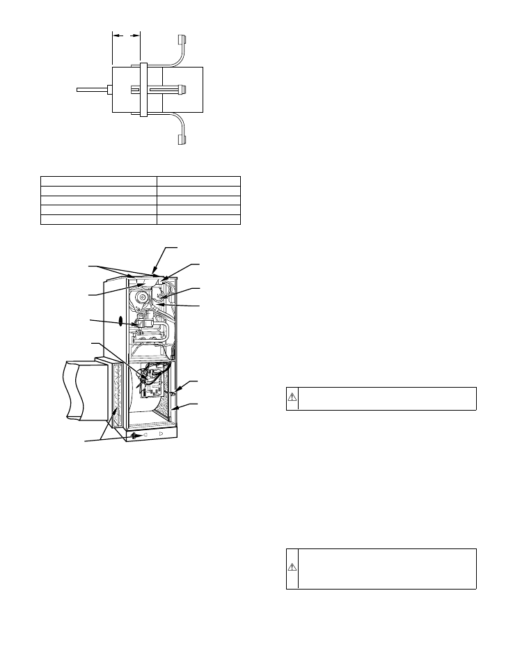
Fig. 3—Motor Belly Band Location
DIMENSIONS (IN.)
FURNACE SIZE
D
036060
1
048080
1–1/2
060100
3
060120
3
A95268
D
Fig. 4—Upflow/Horizontal Component Identification
A00293
BLOCKED
VENT
SAFEGUARD
FLUE
COLLECTOR
BOX
MOUNTING
SCREWS
RELIEF
BOX
CONTROL
FILTER
RETAINER
WASHABLE
FILTER
FURNACE
FLUE
COLLAR
PRESSURE
SWITCH
GAS
VALVE
C
OM
24V
HUM
G
R
Y
W
WASHABLE
FILTER OR
DISPOSIBLE
MEDIA FILTER
IN FILTER
CABINET
—3—