Black & Decker FS1300CSL User Manual
Page 9
9
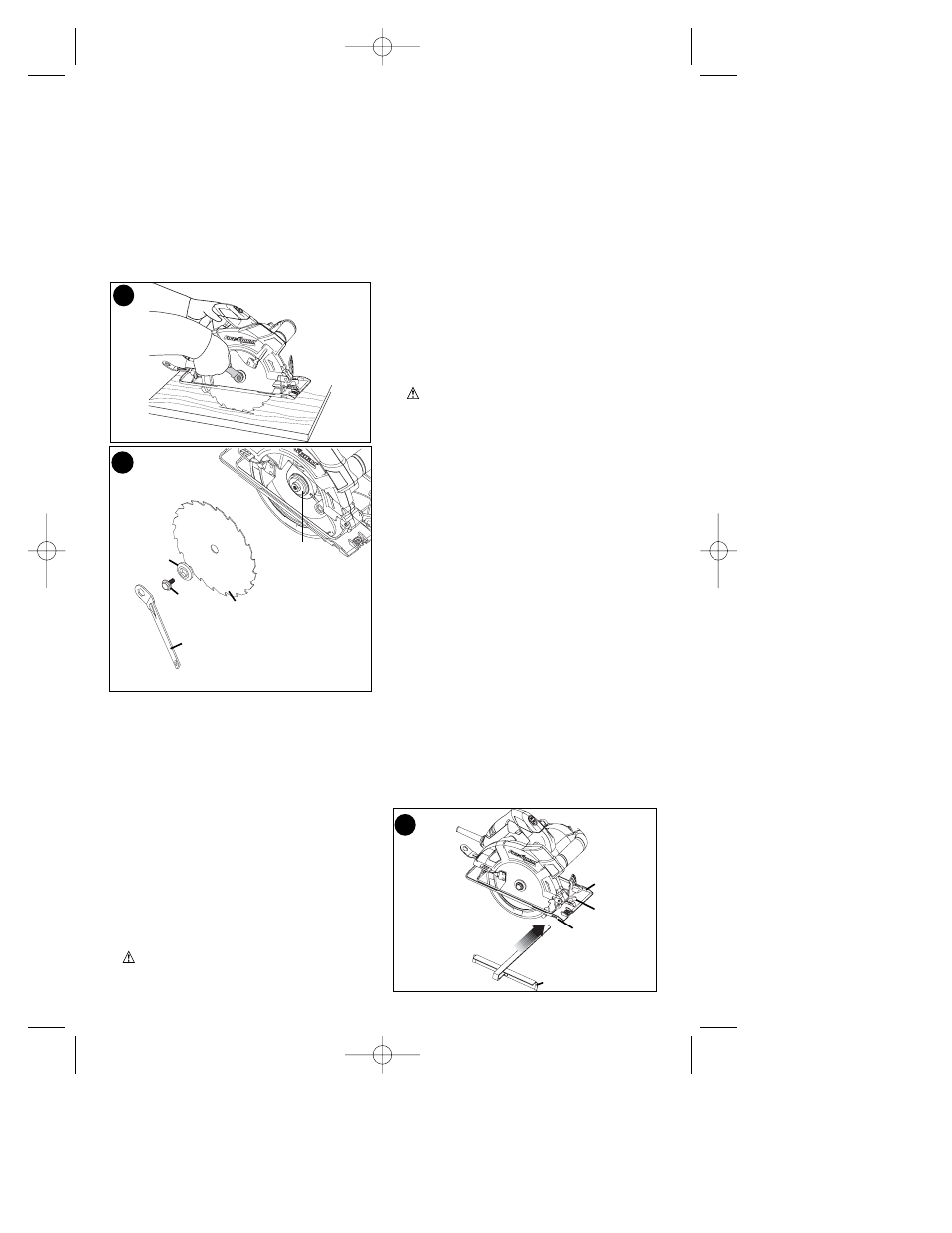
REMOVING THE BLADE (FS1300CSL)
(FIG. 12 & 13)
• Prevent spindle rotation by engaging
the teeth of the saw blade into a piece
of scrap wood.
• Loosen and remove the blade retaining
screw (16) by turning it counter-
clockwise using the wrench (10)
supplied.
• Remove the outer washer (17).
• Remove the saw blade (7).
ATTACHING THE BLADE (FS1300CSL)
• Place the saw blade (7) onto the inner
flange (18), making sure that the arrow
on the blade points in the same
direction as the arrow on the tool.
• Fit the outer washer (17) on the
spindle, with the raised part pointing
away from the saw blade.
• Insert the blade retaining screw (16)
into the hole.
• Prevent spindle rotation by engaging
the teeth of the saw blade into a piece
of scrap wood.
• Securely tighten the blade retaining
screw by turning it clockwise using the
wrench (10) supplied.
WARNING: To reduce the risk of
serious personal injury, read, understand
and follow all important safety warnings
and instructions prior to using tool.
GENERAL CUTS (IMPORTANT: READ
SAFETY WARNINGS AND
INSTRUCTIONS. )
GUARD AGAINST KICKBACK
With unit unplugged, follow all assembly,
adjustment and set up instructions.
Make sure lower guard operates. Select
the proper blade for the material to be cut.
• Measure and mark work for cutting.
• Support and secure work properly (See
Safety Rules and Instructions).
• Use appropriate and required safety
equipment (See Safety Rules).
• Secure and maintain work area (See
Safety Rules).
• With plug inserted and guard closed,
make sure switch turns saw on and off.
WARNING: It is important to support
the work properly and to hold the saw
firmly to prevent loss of control which
could cause personal injury. Figure 3
illustrates recommended hand position.
ATTACHING AND REMOVING THE RIP
FENCE (INCLUDED WITH FS1500CSL)
(FIG. 14)
The rip fence is used to saw in a straight
line parallel to the edge of the workpiece.
ATTACHING
• Loosen the locking knob (19).
• Insert the rip fence (20) through the
openings (21).
• Slide the rip fence into the desired
position.
• Tighten the locking knob.
REMOVING
• Loosen the locking knob.
• Pull the rip fence out of the tool.
NOTE: If you do not have a proper fitting
fence, use a straight edge guide in contact
with the edge of the shoe to improve
accuracy of cut and reduce the possibility
of binding and kickback.
14
13
10
16
17
7
18
12
19
21
20
21
642742-00 01 FS1300 FS1500CSL 11/29/07 2:18 PM Page 9