Behringer T1954 User Manual
Page 9
9
TUBE ULTRAFEX T1954
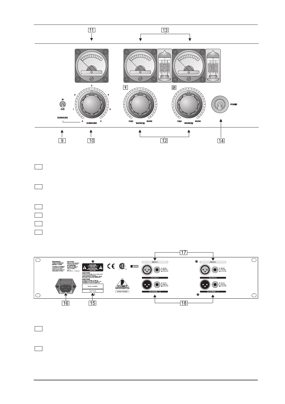
Fig. 1.3: Control elements of the surround and tube section
9
With the SURROUND IN/OUT switch you can activate the surround section. Please note that this
switch has to be released if you want to process two separate input signals. Otherwise there will be
undesired cross-talk between the two channels.
10
The SURROUND control determines the effect of the Surround processor. This function serves to im-
prove the intensity of the stereo effect and to enlarge the stereo basis dependent on the program
content. Therefore, this function can only be used in conjunction with stereo program material.
11
The SURROUND METER enables you to immediately monitor the effect of the Surround Processor.
12
The WARMTH control adjusts the amount of upper harmonics added to the original signal.
13
The WARMTH METER allows you to monitor the amount of added upper harmonics.
14
The POWER switch activates the TUBE ULTRAFEX. If the unit is switched off, it is bypassed and the
input signal is connected to the outputs of your TUBE ULTRAFEX.
Fig. 1.4: The rear panel elements of the TUBE ULTRAFEX
15
SERIAL NUMBER. Please take the time to have the warranty card filled out completely and return it
within 14 days after the date of purchase, so as to be entitled to benefit from our extended warranty.
Alternatively, you can register online at our website under www.behringer.com.
16
FUSE HOLDER/VOLTAGE SELECTOR. Please make sure that your local voltage matches the voltage
indicated on the unit, before you attempt to connect and operate the TUBE ULTRAFEX. In many units
the fuse holder can be installed in one of two positions, allowing you to switch between 230 V and 115 V.
If you wish to operate a unit outside Europe at 115 V, then a stronger fuse must be used (see chapter 6
SPECIFICATIONS). Blown fuses may only be replaced by fuses of the same type and rating.
1. INTRODUCTION