Behringer T1954 User Manual
Page 19
19
TUBE ULTRAFEX T1954
and anode, a current flow is not possible because the unheated anode emits more or less no electrons. This
design was used, for example, as a rectifier in the power supplies of amplifiers. The magnitude and velocity of
the flow of electrons depend on the cathodes temperature, the material it consists of, and the magnitude of the
anode voltage. When the electrons hit the anode they produce heat that is dissipated by using large anode
plates.
Fig. 4.3: Triode
The triode has an additional metal grid between anode and cathode. By applying a negative voltage, this grid
can be used to control the internal resistance of the tube, and hence the anode current. When the grid bias
voltage (voltage between cathode and grid) becomes negative, the current flowing to the anode is reduced
because the negatively charged grid repels the arriving electrons. As a consequence, there are less electrons
to reach the anode. When the bias voltage shifts towards zero, the flow of electrons accelerates. When it finally
becomes zero or even positive, the grid current begins to flow which considerably reduces the current flowing
to the anode and can possibly destroy the tube. Triodes are most commonly used in pre-amps, often in pairs
arranged in one tube (twin triode).
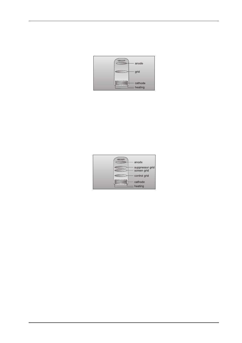
Fig. 4.4: Pentode
In a triode the capacitance between grid and anode is a problem with regard to high frequencies and large
amplification factors. For this reason, the pentode has a positively charged screen grid between the control grid
and the anode. However, the positive charge of the screen grid attracts electrons emitted from the anode plate
when it is hit by arriving electrons. To prevent this electron emission, a decelerating or suppressor grid is
placed between anode and screen grid. As it is negatively charged it blocks the electrons, so that they cannot
reach the screen grid. Pentodes are most commonly used in power stages.
4.6.4 Properties of tubes
In general, the saturation (overdriving) of both transistor and tube-based circuits results in various types of
distortion. These phenomena are quite complex in the real world, but for the sake of a straightforward math-
ematical description we are going to classify them as linear and non-linear distortion. Linear distortion is
produced by frequency-dependent amplification or attenuation processes such as occurs in all kinds of filters
and equalizers. Linear-distortion signals have the same frequency portions both on the input and output sides,
but with different phase positions and amplitudes. Non-linear distortions have additional harmonics and distor-
tion components that were not contained in the original input signal.
For example, when the simplest of all oscillations, a sine wave with a fixed frequency f, is overdriven, new
oscillations with frequencies of 2*f, 3*f, etc. (integral multiples of the original frequency) are produced. These
new frequencies are referred to as upper harmonics grouped as odd and even harmonics.
Unlike the transistor, saturated tubes mostly produce even harmonics which are perceived by the human ear
as more pleasant in sound than odd harmonics. Another important aspect lies in the fact that tubes produce
distortion more gradually than transistors, which is why we speak of the saturation of a Tube Stage. When
4. TECHNICAL BACKGROUND