Behringer T1954 User Manual
Page 8
8
TUBE ULTRAFEX T1954
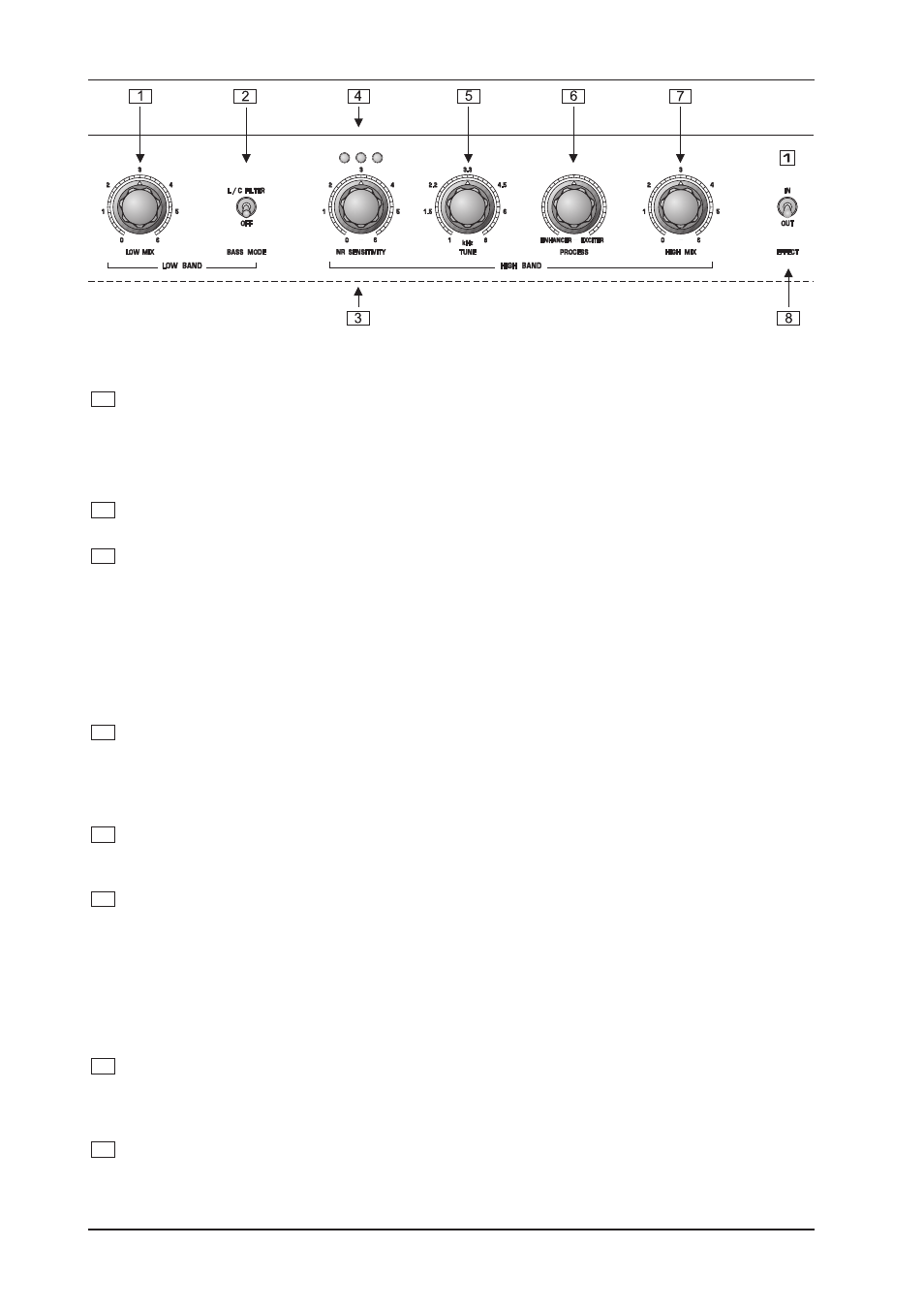
Fig. 1.2: Control elements of the LOW BAND and HIGH BAND section
1
The LOW MIX control of the low band determines the amount of signal used for sound enhancement
(from zero to six). Turn the control clockwise for a more strong and punchy bass sound. The setting
depends on the application you are addressing.
+
Please note that the Bass Processor should be set carefully to avoid possible speaker damage.
Most near-field monitors are not capable of handling the bass produced by the TUBE ULTRAFEX.
2
The LC FILTER switch enables an additonal bass sound. The special L/C filter characteristic supplies a
more dry and punchy bass sound.
3
The NR SENSITIVITY control adapts the sensitivity of the Noise Reduction system to the input level of
the program material. The Noise Reduction system cares for a noise-free performance during breaks in
your program material and removes noise during silent passages. For that the Enhancer/Exciter signal
is dynamically reduced if the input signal falls under the threshold of the NR SENSITIVITY. In combina-
tion with the Noise Reduction system you also edit the sensitivity of the enhancer/exciter function when
using the NR SENSITIVITY control: The more you turn the control clockwise the more the enhancer/
exciter function comes into action. To avoid pumping and to provide an optimum effect of the enhancer/
exciter function take care of a correct setting of the NR SENSITIVITY control. The three LEDs above the
NR SENSITIVITY control will help you to find the right setting.
4
In combination with the NR SENSITIVITY control these three CONTROL LEDs help you to find the
perfect setting of the noise reduction system. The more LEDs illuminate the more effect signal passes
through the noise reduction system. When all three LEDs light up constantly the noise reduction sys-
tem is inactive. In quiet passages only the first LED should light up. Loud signals should cause all LEDs
to light up.
5
The TUNE control sets the cut-off frequency of the high pass filter. Using this control you can select the
frequencies that are routed to the Natural Sonic processor. The cut-off frequency can be adjusted within
a range of 1 to 8 kHz.
6
The PROCESS control determines the function of the device. When turning the control in clockwise
direction, the exciter function is activated, which increases the signals transparency and sharpness.
Consequently, the TUBE ULTRAFEX can be adapted to the program material, to suit the application on
hand as well as any personal sound preferences.
+
Please note that with classical music, acoustic instruments or with output signals that already
include sufficient treble frequencies, the enhancer setting should be preferred. However,
when processing, for instance, a slapped bass guitar, it is the exciter setting which should
dominate.
7
The HIGH MIX control of the high band determines the amount of signal used for sound enhancement
(from zero to six). It would depend on the application as to whether a high-quality system is to be given
the finishing touch with the TUBE ULTRAFEX, or whether maximum intelligibility is to be achieved in a
relatively poor sound reinforcement system.
8
The EFFECT IN/OUT switch activates the complete signal process and tube circuitry. The
TUBE ULTRAFEX features a hard-bypass function. As a result the inputs and outputs are connected
when the unit is switched off. With the EFFECT IN/OUT switch you can compare the processed and the
input signal.
1. INTRODUCTION