Specifications, 310aa v /j a v – Bryant SERIES E A10252 User Manual
Page 4
4
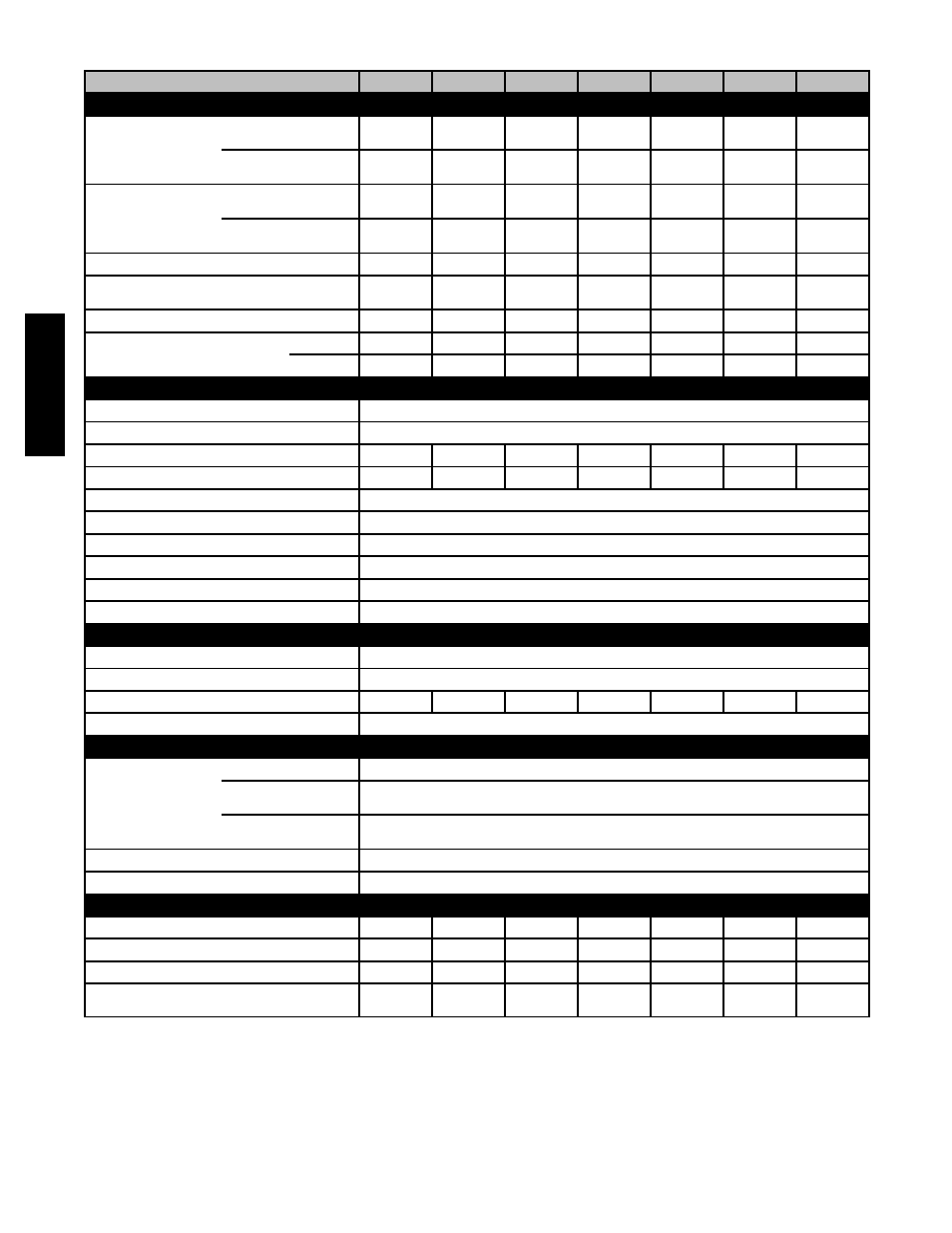
SPECIFICATIONS
UNIT SIZE
024045
036045
024070
036070
048070
042090
048090
RATINGS AND PERFORMANCE
Input Btuh*
310JAV Upflow; all
310AAV
44,000
44,000
66,000
66,000
66,000
88,000
88,000
Nonweatherized ICS
310JAV Downflow/
Horizontal
42,000
42,000
63,000
63,000
63,000
84,000
84,000
Output Capacity
(Btuh)†
310JAV Upflow; all
310AAV
35,000
36,000
53,000
54,000
53,000
71,000
71.000
Nonweatherized ICS
310JAV Downflow/
Horizontal
34,000
34,000
51,000
51,000
51,000
68,000
68,000
AFUE†
80.0
80.0
80.0
80.0
80.0
80.0
80.0
Certified Temperature Rise Range --- ° F (° C)
30-60
(17---33)
20-50
(11---28)
40-70
(22---39)
30-60
(17---33)
25-55
(14---30)
40-70
(22---39)
30-60
(17---33)
Certified External Static Pressure
Heat/Cool
0.10/0.50
0.10/0.50
0.12/0.50
0.12/0.50
0.12/0.50
0.15/0.50
0.15/0.50
Airflow CFM‡
Heating
920
1250
720
1195
1450
1375
1505
Cooling
845
1160
900
1200
1530
1385
1720
ELECTRICAL
Unit Volts---Hertz---Phase
115-60-1
Operating Voltage Range
Min-Max
104-127
Maximum Unit Amps
5.4
7.0
5.0
6.8
9.5
8.2
10.0
Maximum Wire Length (Measure 1 Way in Ft (M)
49 (14.9)
39 (11.8)
52 (15.8)
40 (12.1)
29 (8.8)
34 (10.3)
28 (8.5)
Minimum Wire Size
14
Maximum Fuse or Ckt Bkr Size (Amps)**
15
Transformer (24v)
40va
External Control
Heating
12va
Power Available
Cooling
35va
Air Conditioning Blower Relay
Standard
CONTROLS
Limit Control
SPST
Heating Blower Control
Solid-State Time Operation
Burners (Monoport)
2
2
3
3
3
4
4
Gas Connection Size
1/2-in. NPT
GAS CONTROLS
Gas Valve (Redundant)
Mfr.
White-Rodgers
Min. inlet pressure
(In. W.C.)
4.5 (Natural Gas)
Max. inlet pressure
(In. W.C.)
13.6 (Natural Gas)
Ignition Device
Hot Surface
Factory-installed orifice
Size 43
BLOWER DATA
Direct-Drive Motor HP (PSC)
1/5
1/3
1/5
1/3
1/2
1/3
1/2
Motor Full Load Amps
2.9
5.2
2.9
5.2
7.9
5.2
7.9
RPM (Nominal)-Speeds
1075-3
1075-3
1075-3
1075-3
1075-3
1075-3
1075-3
Blower Wheel Diameter x Width --- In. (mm)
10 x 6
(254 x 152)
10 x 6
(254 x 152)
10 x 6
(254 x 152)
10 x 6
(254 x 152)
11 x 8
(279 x 203)
10 x 8
(254 x 203)
10 x 10
(254 x 254)
*
Gas input ratings are certified for elevations to 2000 ft. (610 M). In USA, For elevations above 2000 ft (610 M), reduce ratings 4 percent for each 1000 ft (305
M) above sea level. Refer to National Fuel Gas Code NFPA 54/ANSI Z223.1---2009 Table F.4 or furnace installation instructions.
†
Capacity in accordance with U.S. Government DOE test procedures.
‡
Airflow shown is for bottom only return-air supply for the as-shipped speed tap. For air delivery above 1800 CFM, see Air Delivery table for other options. A
filter is required for each return-air supply. An airflow reduction of up to 7 percent may occur when using the factory-specified 4-5/16---in. (110 mm) wide,
high efficiency media filter.
** Time---delay type is recommended.
ICS Isolated Combustion System
310AA
V
/J
A
V