Connection diagram, Connecting the units – Pioneer RS-A9 User Manual
Page 62
61
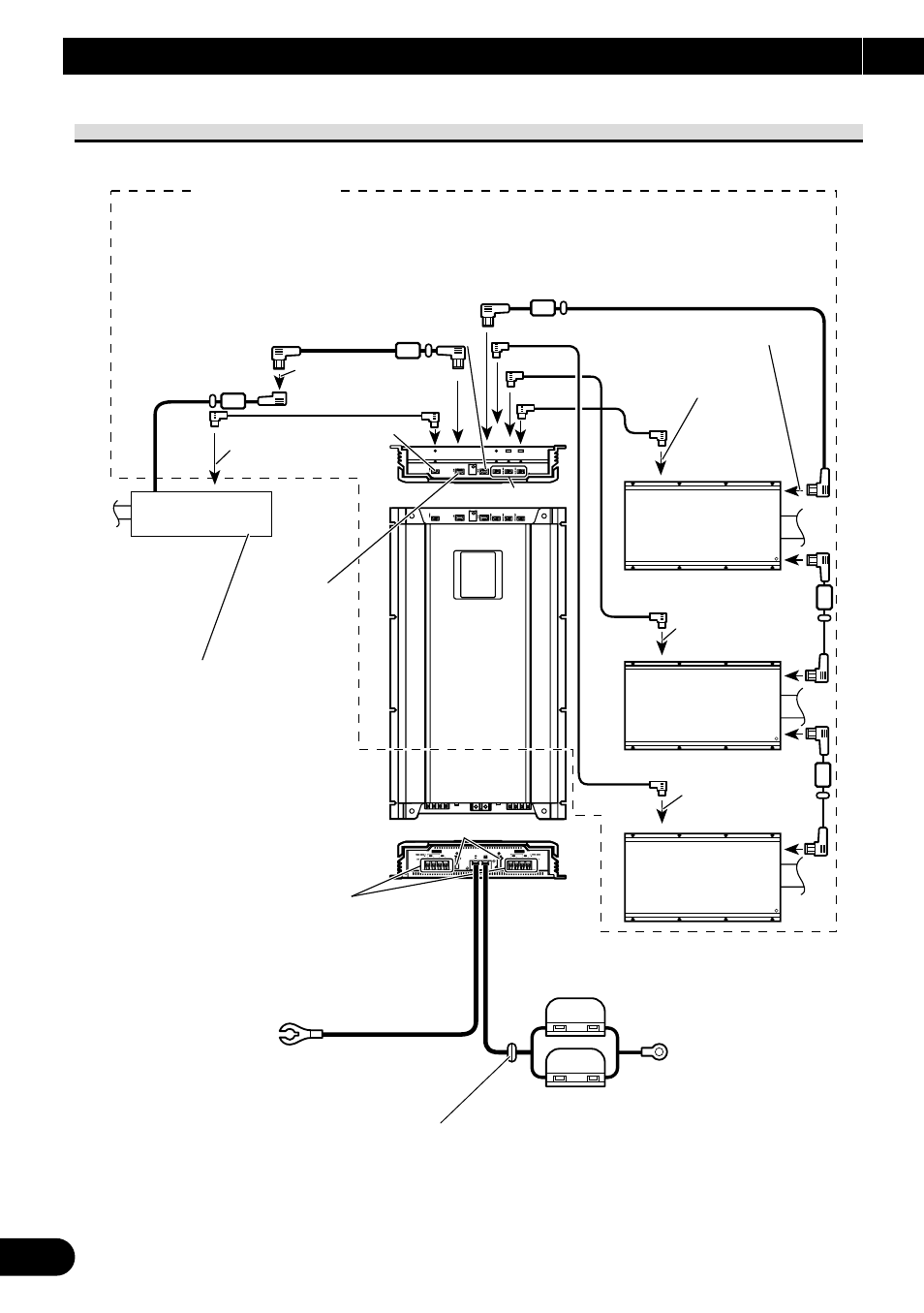
Connection Diagram
*1 IP-BUS cable (supplied)
*2 Optical cable (supplied)
*3 IP-BUS cable (supplied with RS-A7)
*4 Optical cable (supplied with RS-A7)
*1
*3
*3
*3
*2
*4
*4
*4
Optical input
Optical out
Speaker output terminal
See the “Connecting the Speaker
wires” section for speaker
connection instructions.
RS-A7
(sold separately)
IP-BUS input
(blue)
Black
To optical input
To optical input (blue)
To IP-BUS input (blue)
(blue)
(black)
Fuse (25 A)
Refer to RS-D7R
owner's manual
Optical out (Black)
IP-BUS out (black)
Ground wire (Black) [RD-223] (sold separately)
Connect to metal body or chassis.
fuse (30 A)
× 2
6 m
1 m
RS-A7
(sold separately)
RS-A7
(sold separately)
Special red battery wire [RD-223]
(sold separately)
After making all other connections at the
amplifier, connect the battery wire terminal of
the amplifier to the positive (+) terminal of the
battery.
(blue)
(black)
To optical input
Red
Audio system
Grommet
Connecting the Units
- PRS-X340 (88 pages)
- ND-G500 (44 pages)
- RS-A7 (142 pages)
- GM-X554 (76 pages)
- GM-X574 (88 pages)
- PRS-D1100M (113 pages)
- PRS-D1100M (8 pages)
- GM-X952 (32 pages)
- PRS-D210 (86 pages)
- GM-X642 (64 pages)
- GM-X562 (76 pages)
- PRS-A700 (74 pages)
- GM-X564 (76 pages)
- PRS-A500 (62 pages)
- AVIC-S2 RU (45 pages)
- AVIC-S2 RU (153 pages)
- AVIC-S2 RU (84 pages)
- AVH-2300DVD (8 pages)
- AVH-2300DVD (64 pages)
- DEH-P6600R (103 pages)
- AVIC-F50BT (104 pages)
- AVIC-F50BT (180 pages)
- AVIC-F50BT (208 pages)
- AVIC-F850BT (200 pages)
- AVIC-F50BT (2 pages)
- AVIC-F50BT (168 pages)
- AVIC-F50BT (132 pages)
- AVIC-900DVD (30 pages)
- AVIC-900DVD (74 pages)
- AVIC-900DVD (172 pages)
- AVIC-900DVD (190 pages)
- AVH-1400DVD (76 pages)
- AVH-1400DVD (76 pages)
- AVH-P3400DVD (112 pages)
- AVH-1400DVD (8 pages)
- CNSD-110FM-Russian (32 pages)
- AVIC-F860BT (132 pages)
- AVIC-F860BT (216 pages)
- AVIC-F30BT (128 pages)
- AVIC-F30BT (124 pages)
- AVIC-F930BT (192 pages)
- AVIC-F940BT (28 pages)
- AVIC-F30BT (172 pages)
- AVIC-F30BT (100 pages)