Connections, Fixed slot (slot 1 & 2), Which signals can be connected to slot 1 & 2 – Barco R9002790 User Manual
Page 24: Pin assignment for the dvi connector, How to select input slot 1 or 2
4-5
Connections
R5976336 BARCOSLM R6 Executive 06092001
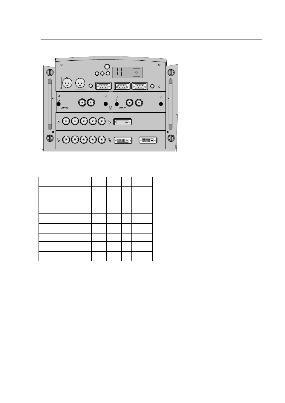
Fixed Slot (slot 1 & 2)
Slot 1 & 2 has 5 BNC input terminals for 5 cable input and a DVI plug for DVI input. Slot 1 has also an DVI output for loop through
to a second projector. Within the installation mode it is possible to setup the input for 5 cable or DVI (panellink).
Which signals can be connected to slot 1 & 2 ?
The following signals can be connected to BNC connectors (5 cable in put):
Connector name
R
G
B
H
V
Input signal
RGBHV
R
G
B
H
V
RGBS
R
G
B
S
-
RGsB
R
Gs
B
-
-
Composite Video
-
Video -
-
-
Super Video
-
Y
-
-
C
Component Video - SS
R-Y
Y
B-Y S
-
Component Video - SOY
R-Y
Ys
B-Y -
-
DVI signals (panellink) can be connected to the DVI input connector.
Pin assignment for the DVI connector
Pin 1
TMDS DATA2-
Pin 9
TMDS DATA1-
Pin 17
TMDS DATA0-
Pin 2
TMDS DATA2+
Pin 10
TMDS DATA1+
Pin 18
TMDS DATA0+
Pin 3
TMDS DATA2/4 Shield Pin 11
TMDS DATA1/3 Shield
Pin 19
TMDS DATA0/5 Shield
Pin 4
TMDS DATA4-
Pin 12
TMDS DATA3-
Pin 20
TMDS DATA5-
Pin 5
TMDS DATA4+
Pin 13
TMDS DATA3+
Pin 21
TMDS DATA5+
Pin 6
DDC Clock
Pin 14
+5 Power
Pin 22
TMDS Clock Shield
Pin 7
DDC Data
Pin 15
Ground (for +5V)
Pin 23
TMDS Clock+
Pin 8
No connect
Pin 16
Hot Plug Detect
Pin 24
TMDS Clock-
How to select input Slot 1 or 2 :
Key in 1 or 2 on the RCU or the local keypad.
Selection of the signal format on the 'Input slot' menu.
PVU
DIÃ
P
5
C9ÃT9DÃ9DBDU6GÃHP9VG@
PVU
DIÃ
P
T9DÃ9DBDU6GÃDIQVU
8PHHÃQPSU
USDBB@SÃPVU
ST!"!#!!ÃPVU
ST!"!#!!ÃDI
DSSrprvr
9vhtvpÃ8qr
B rrÃPr hv
SrqÃThqi
DS
TpÃPF
Ch qv rq
rr
8USGÃ
Ch qv rq
rr
8USGÃ!
UÃh
uh qv rq
rr
8USGÃ"
P
P
P
P
9WDÃDIQVU
9WDÃDIQVU
9WDÃPVUQVU
CvtuÃ7hqvquГГ$Г867G@ÃDIQVU
CvtuÃ7hqvquГГ$Г867G@ÃDIQVU
S
B
7
C8
W
S
B
7
C8
W