Lenovo ThinkServer RD650 User Manual
Page 94
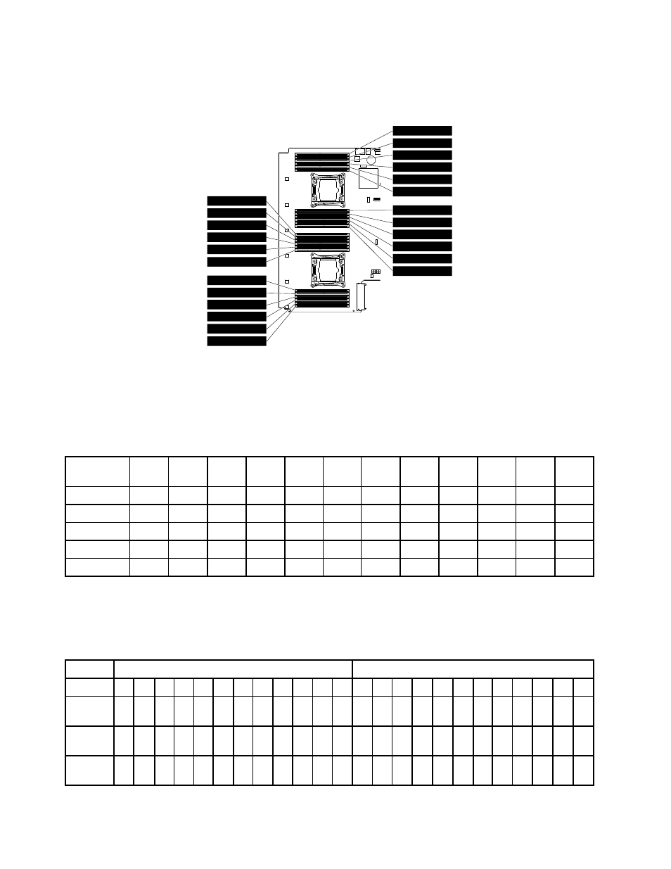
The following illustration helps you to locate the memory slots on the system board. The following illustration
shows the system board with two installed microprocessors (also known as CPU).
CPU1 DIMMC1
CPU1 DIMMC2
CPU1 DIMMC3
CPU1 DIMMD1
CPU1 DIMMD2
CPU1 DIMMD3
CPU1 DIMMB3
CPU1 DIMMB2
CPU1 DIMMB1
CPU1 DIMMA3
CPU1 DIMMA2
CPU1 DIMMA1
CPU2 DIMMC1
CPU2 DIMMC2
CPU2 DIMMC3
CPU2 DIMMD1
CPU2 DIMMD2
CPU2 DIMMD3
CPU2 DIMMB3
CPU2 DIMMB2
CPU2 DIMMB1
CPU2 DIMMA3
CPU2 DIMMA2
CPU2 DIMMA1
Figure 50. Memory slots on the system board
The following table provides information about the memory module installation rules for servers that have
only one microprocessor (CPU1) installed. The “X” mark indicates the memory slots into which the memory
modules should be installed in different situations.
Table 2. Memory module installation rules for servers with one microprocessor
CPU1
DIMM
A1
A2
A3
B1
B2
B3
C1
C2
C3
D1
D2
D3
1 DIMM
X
2 DIMMs
X
X
4 DIMMs
X
X
X
X
8 DIMMs
X
X
X
X
X
X
X
X
12 DIMMs
X
X
X
X
X
X
X
X
X
X
X
X
The following table provides information about the memory module installation rules for servers that have
two microprocessors (CPU1 and CPU2) installed. The “X” mark indicates the memory slots into which the
memory modules should be installed in different situations.
Table 3. Memory module installation rules for servers with two microprocessors
CPU1 DIMM
CPU2 DIMM
A1 A2 A3 B1 B2 B3 C1 C2 C3 D1 D2 D3 A1 A2 A3 B1 B2 B3 C1 C2 C3 D1 D2 D3
2
DIMMs
X
X
4
DIMMs
X
X
X
X
8
DIMMs
X
X
X
X
X
X
X
X
80
ThinkServer RD650 User Guide and Hardware Maintenance Manual