1 overview overview overview overview overview – Asus A8V-E User Manual
Page 34
2 - 1 0
2 - 1 0
2 - 1 0
2 - 1 0
2 - 1 0
C h a p t e r 2 : H a r d w a r e i n f o r m a t i o n
C h a p t e r 2 : H a r d w a r e i n f o r m a t i o n
C h a p t e r 2 : H a r d w a r e i n f o r m a t i o n
C h a p t e r 2 : H a r d w a r e i n f o r m a t i o n
C h a p t e r 2 : H a r d w a r e i n f o r m a t i o n
2.4
System memory
2.4.1
2.4.1
2.4.1
2.4.1
2.4.1
Overview
Overview
Overview
Overview
Overview
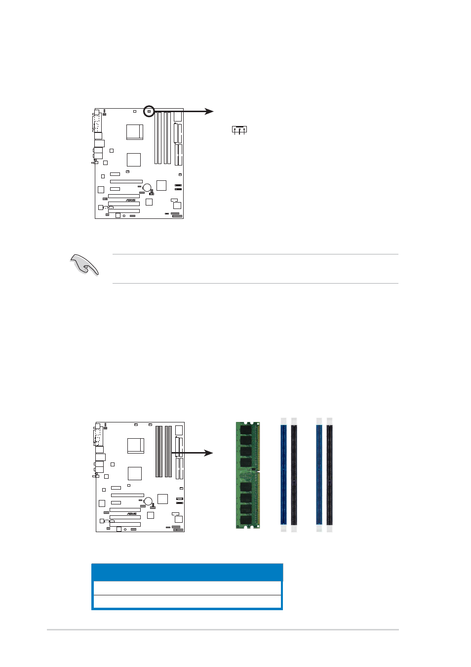
The motherboard comes with four 184-pin Double Data Rate (DDR) Dual
Inline Memory Modules (DIMM) sockets.
The following figure illustrates the location of the sockets:
C h a n n e l
C h a n n e l
C h a n n e l
C h a n n e l
C h a n n e l
S o c k e t s
S o c k e t s
S o c k e t s
S o c k e t s
S o c k e t s
Channel A
DIMM_A1 and DIMM_A1
Channel B
DIMM_B1 and DIMM_B2
3.
When the fan and heatsink assembly is in place, connect the CPU fan
cable to the connector on the motherboard labeled CPU_FAN.
Do not forget to connect the CPU fan connector! Hardware monitoring
errors can occur if you fail to plug this connector.
A8V-E
DELUXE
®
A8V-E DELUXE CPU_Fan connector
CPU_FAN
GND
Rotation
+12V
A8V-E
DELUXE
®
A8V-E DELUXE 184-pin DDR DIMM sockets
DIMM_A1
DIMM_A2
DIMM_B1
DIMM_B2