English, Top mount, Bottom mount – Vollrath Hot Cold Drop-ins 4 WELL User Manual
Page 3
3
ENGLISH
O
peratOr
’
s
M
anual
C
ontrol
B
ox
m
ounting
Controls must be mounted on the operator side (raceway side) for proper
orientation with wells. The control box requires 3″ of depth in the cabinet
when using the included frame. Without the frame, the control box requires
4″ of depth in the cabinet.
C
ontrol
B
ox
C
utout
D
imensions
Model
Cutout Dimension
One Well Drop-in
7" x 8”
Two Well Drop-in
7" x 10-1/2"
Three Well Drop-in
7" x 13"
Four Well Drop-in
7" x 15-1/2"
C
ontrol
B
ox
l
oCations
Figure 4. Two well drop-in control box mounting
Figure 5. Three well drop-in control box mounting
Figure 6. Four well drop-in control box mounting
H
ot
/C
olD
W
ell
D
rop
-
in
C
utout
D
imensions
Model
Cutout Dimension
One Well Top Mount Drop-in
25-1/4" x 17-5/16"
One Well Bottom Mount Drop-in
Per customer specification for
amount of visible top flange
Two Well Drop-in
25-1/4" x 40-3/4"
Three Well Drop-in
25-1/4" x 54"
Four Well Drop-in
25-1/4" x 67-1/4"
NOTE: Well cutouts must have a corner radius of 7/8".
NOTE: Control cutouts must have a corner radius of 3/8".
s
eal
tHe
F
lange
Top Mount
1. Place a bead of silicone sealer rated at a minimum of 450 °F (232 °C)
around the well flange to prevent water from leaking into control areas.
2. Set the clips into slots
3. Tighten the thumbscrews slowly and in an alternating pattern to evenly
compress the silicone.
Bottom Mount
Place a bead of silicone sealer rated at a minimum of 450 °F (232 °C)
between the countertop and the inside of the well to prevent water from
leaking into control areas, and in mounting holes when using rivets or other
fasteners.
c
ontrolS
10
9
8
7
6
5
4
3
2
1
0
10
9
8
7
6
5
4
3
2
1
0
10
9
8
7
6
5
4
3
2
1
0
A
E
D
C
B
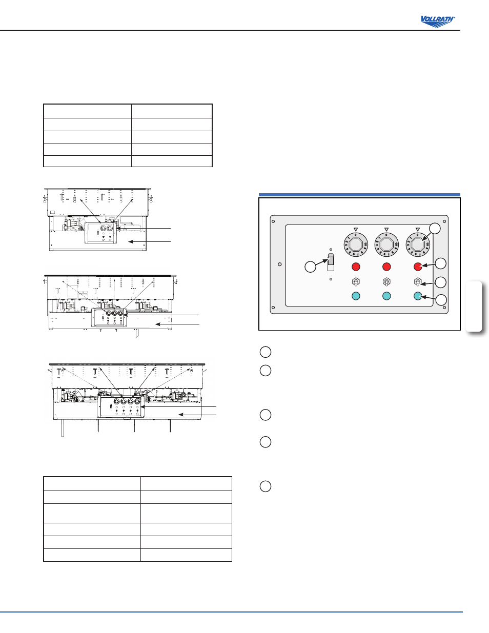
Figure 7. Controls.
A
ON/OFF SWITCH. Switches the equipment power “ON” or “OFF”.
B
MODE SELECTOR SWITCH. The down position selects refrigeration
mode. The up position selects heating mode The center position
selects neutral mode. When the switch is in the center or up positions,
the drain valve will be closed.
C
REFRIGERATION INDICATOR LIGHT. Illuminates when the unit is in
the refrigeration mode.
D
TEMPERATURE CONTROL DIAL (Hot Mode Only). Used to set
or adjust the hot temperature of the well. The higher the number
the higher the temperature, the lower the number the lower the
temperature.
E
HEATING INDICATOR LIGHT. Illuminates when the unit is in the
heating mode.
Control Box
Raceway
Control Box
Raceway
Control Box
Raceway