Dimensions, Clevis and trunnion mounting cylinder dimensions, These dimensions** affected by rod size – Sheffer A SERIES User Manual
Page 5: These dimensions affected by stroke, These dimensions** affected by rod size and stroke
Mounting Information
Clevis Mount Cylinders are
furnished with a hard chrome
plated clevis pin and retainers.
For a complete line of accessories
(rod eyes, rod clevises, clevis and
pivot mounting brackets, jam
nuts, and pins) designed for use
with Sheffer cylinders, see
separate Accessories Brochure.
All clevis and trunnion cylinders
need provision on both ends for
pivoting in one direction.
Alignment in the other direction
is essential in order to avoid
excessive side loading. Where
two-direction pivoting is
necessary, contact our Distributor
for specific recommendations.
Trunnion Pins on trunnion
mount cylinders are designed for
shear loads only, not bending
loads. Customer trunnion pin
pillow blocks should be rigid and
mounted as close to the head as
possible. Bearing should be
provided for the full length of the
trunnion pin. Lubrication should
be provided to the pins. Trunnion
pins are an integral part of the
ring on the intermediate trunnion
mount. Mounting position
(Dimension XI) of the
intermediate trunnion must be
given on order.
1
1
/
8
" THRU 6" BORES
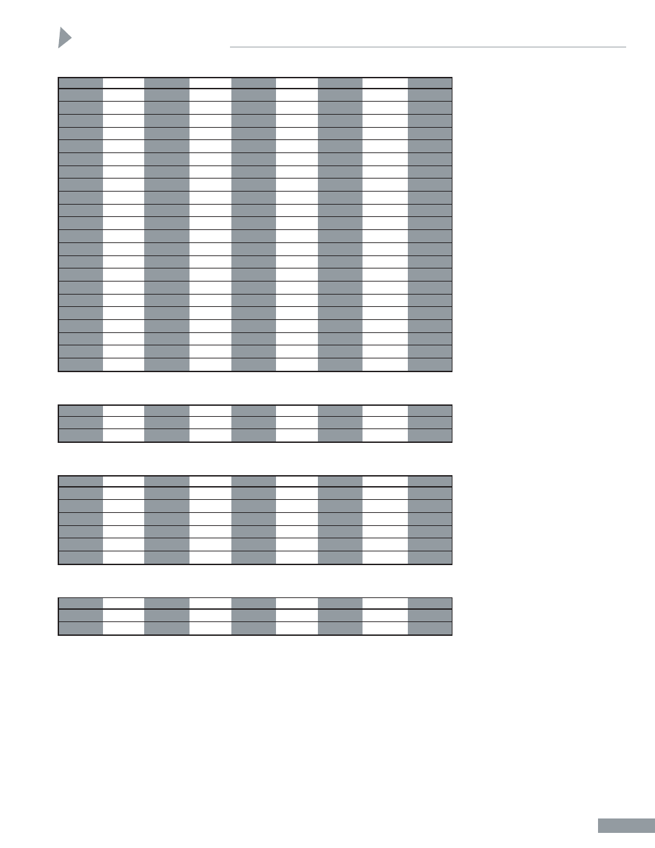
Dimensions
Clevis and Trunnion Mounting Cylinder Dimensions
A-4
BORE
1
1
/
8
1
1
/
2
2
2
1
/
2
3
1
/
4
4
5
6
CB
5
/
8
3
/
4
3
/
4
3
/
4
1
1
/
4
1
1
/
4
1
1
/
4
1
1
/
2
CD
3
/
8
1
/
2
1
/
2
1
/
2
3
/
4
3
/
4
3
/
4
1
CL
1
1
/
4
1
3
/
4
1
3
/
4
1
3
/
4
2
1
/
2
2
1
/
2
2
1
/
2
3
CW
5
/
16
1
/
2
1
/
2
1
/
2
5
/
8
5
/
8
5
/
8
3
/
4
E
1
3
/
4
2
2
1
/
2
3
3
3
/
4
4
1
/
2
5
1
/
2
6
1
/
2
EE NPTF
1
/
4
3
/
8
3
/
8
3
/
8
1
/
2
1
/
2
1
/
2
3
/
4
F
3
/
8
3
/
8
3
/
8
3
/
8
5
/
8
5
/
8
5
/
8
3
/
4
G
1
3
/
32
1
15
/
32
1
3
/
8
1
3
/
8
1
5
/
8
1
5
/
8
1
5
/
8
1
7
/
8
J
27
/
32
31
/
32
7
/
8
7
/
8
1
1
/
8
1
1
/
8
1
1
/
8
1
3
/
8
K
7
/
32
7
/
32
1
/
4
1
/
4
5
/
16
5
/
16
7
/
16
7
/
16
L
15
/
16
3
/
4
3
/
4
3
/
4
1
1
/
4
1
1
/
4
1
1
/
4
1
1
/
2
LR
7
/
16
1
/
2
1
/
2
1
/
2
3
/
4
3
/
4
3
/
4
1
MM
1
/
2
5
/
8
5
/
8
5
/
8
1
1
1
1
3
/
8
MR
3
/
8
1
/
2
1
/
2
1
/
2
3
/
4
3
/
4
3
/
4
1
TA
7
/
8
1
1
/
4
1
1
/
2
1
3
/
4
2
1
/
4
2
1
/
2
3
3
5
/
8
TB
1
3
/
4
2
1
/
2
3
3
1
/
2
4
1
/
2
5
6
7
1
/
4
TD
3
/
4
1
1
1
1
1
1
1
3
/
8
TL
3
/
4
1
1
1
1
1
1
1
3
/
8
TM
1
3
/
4
2
1
/
2
3
3
1
/
2
4
1
/
2
5
1
/
4
6
1
/
4
7
5
/
8
TT
1
1
1
/
2
1
1
/
2
1
1
/
2
1
3
/
4
2
2
2
1
/
2
UM
3
1
/
4
4
1
/
2
5
5
1
/
2
6
1
/
2
7
1
/
4
8
1
/
4
10
3
/
8
UT
3
1
/
4
4
4
1
/
2
5
5
3
/
4
6
1
/
2
7
1
/
2
9
1
/
4
These Dimensions** Affected By Rod Size
BORE
1
1
/
8
1
1
/
2
2
2
1
/
2
3
1
/
4
4
5
6
XG
1
23
/
32
1
15
/
16
1
15
/
16
1
15
/
16
2
7
/
16
2
7
/
16
2
7
/
16
2
13
/
16
Y
1
23
/
32
1
15
/
16
1
15
/
16
1
15
/
16
2
7
/
16
2
7
/
16
2
7
/
16
2
13
/
16
These Dimensions Affected By Stroke
BORE
1
1
/
8
1
1
/
2
2
2
1
/
2
3
1
/
4
4
5
6
LB
3
3
/
4
4
4
4
1
/
8
4
7
/
8
4
7
/
8
5
1
/
8
5
3
/
4
P
2
3
/
16
2
1
/
4
2
1
/
4
2
3
/
8
2
5
/
8
2
5
/
8
2
7
/
8
3
1
/
8
These Dimensions** Affected By Rod Size and Stroke
BORE
1
1
/
8
1
1
/
2
2
2
1
/
2
3
1
/
4
4
5
6
XC
5
5
/
16
5
3
/
8
5
3
/
8
5
1
/
2
6
7
/
8
6
7
/
8
7
1
/
8
8
1
/
8
XI (MIN)
2
19
/
32
3
7
/
32
3
1
/
8
3
1
/
8
3
7
/
8
4
4
4
3
/
4
XI (MAX)
3
1
/
32
2
29
/
32
3
3
1
/
8
3
5
/
8
3
1
/
2
3
3
/
4
4
XJ
3
29
/
32
4
3
/
16
4
3
/
16
4
5
/
16
5
1
/
16
5
1
/
16
5
5
/
16
5
15
/
16
ZB
4
19
/
32
4
27
/
32
4
7
/
8
5
5
15
/
16
5
15
/
16
6
5
/
16
7
1
/
16
ZC
5
11
/
16
5
7
/
8
5
7
/
8
6
7
5
/
8
7
5
/
8
7
7
/
8
9
1
/
8
For rod end information see Pages A-17 and A-18
**Dimensions shown are for standard rod size only. For oversize and 2:1 rods, add N dimension
shown on rod end chart, Page A-17.