Dimensions, A-14, These dimensions** affected by rod size and stroke – Sheffer A SERIES User Manual
Page 15: These dimensions** affected by rod size, These dimensions affected by stroke
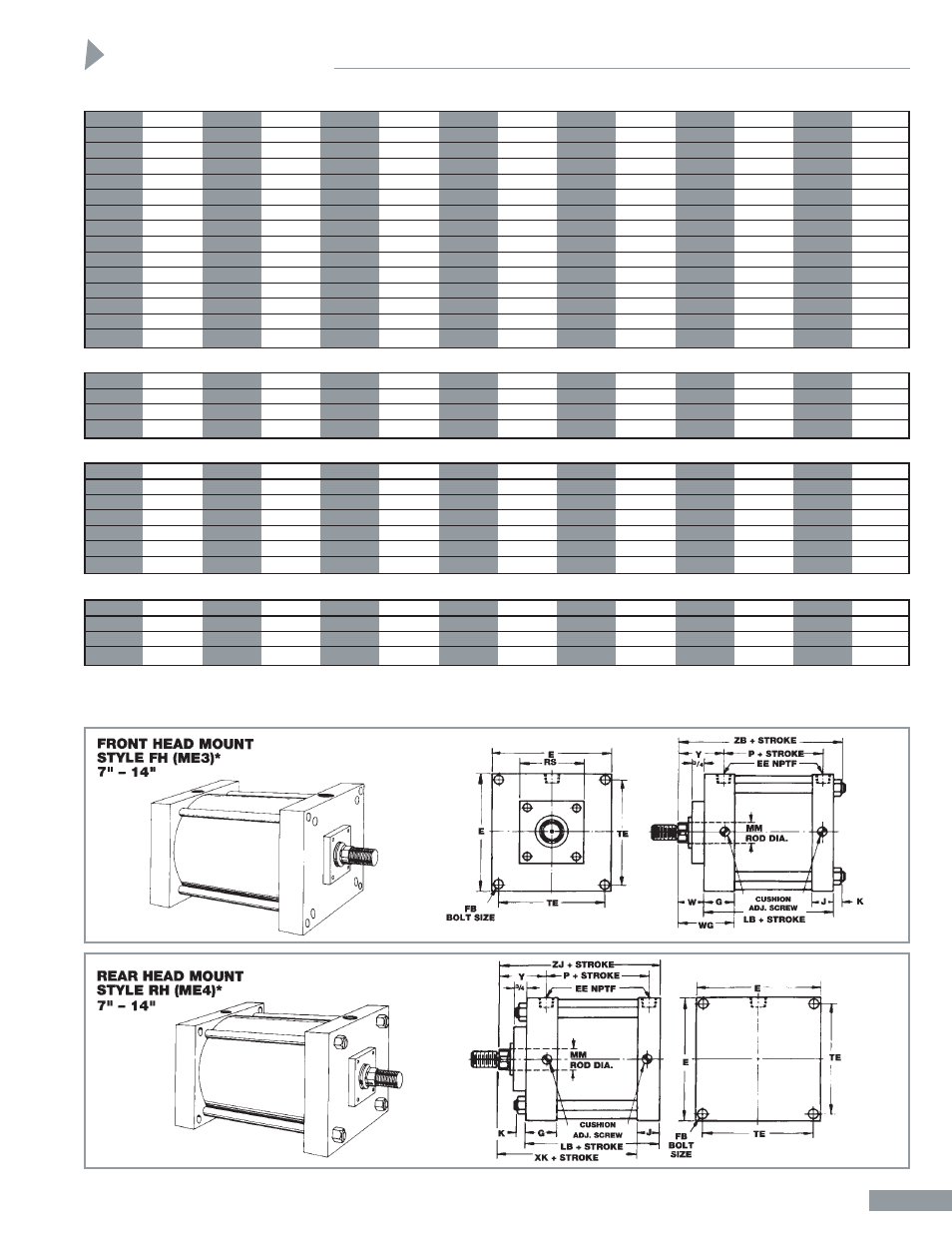
*Number in parenthesis ( ) is ANSI Standard No. B93.1-64 Mounting Style Designation.
1
1
/
8
" THRU 14" BORES
Dimensions
Head, Tie Rod and Basic Double Rod Cylinder Dimensions
A-14
BORE
1
1
/
8
1
1
/
2
2
2
1
/
2
3
1
/
4
4
5
6
7
8
10
12
14
AA
1.68
2.02
2.6
3.1
3.9
4.7
5.8
6.9
8.1
9.1
11.2
13.3
15.4
BB
1
1
1
1
/
8
1
1
/
8
1
3
/
8
1
3
/
8
1
13
/
16
1
13
/
16
2
5
/
16
2
5
/
16
2
11
/
16
2
11
/
16
3
3
/
16
DD
1
/
4
-28
1
/
4
-28
5
/
16
-24
5
/
16
-24
3
/
8
-24
3
/
8
-24
1
/
2
-20
1
/
2
-20
5
/
8
-18
5
/
8
-18
3
/
4
-16
3
/
4
-16
7
/
8
-14
E
1
3
/
4
2
2
1
/
2
3
3
3
/
4
4
1
/
2
5
1
/
2
6
1
/
2
7
1
/
2
8
1
/
2
10
5
/
8
12
3
/
4
14
3
/
4
EE NPTF
1
/
4
3
/
8
3
/
8
3
/
8
1
/
2
1
/
2
1
/
2
3
/
4
3
/
4
3
/
4
1
1
1
1
/
4
F
3
/
8
3
/
8
3
/
8
3
/
8
5
/
8
5
/
8
5
/
8
3
/
4
—
—
—
—
—
FB*
—
—
—
—
—
—
—
—
1
/
2
5
/
8
3
/
4
3
/
4
7
/
8
G
1
3
/
32
1
15
/
32
1
3
/
8
1
3
/
8
1
5
/
8
1
5
/
8
1
5
/
8
1
7
/
8
1
7
/
8
1
7
/
8
2
1
/
8
2
3
/
16
2
7
/
8
J
27
/
32
31
/
32
7
/
8
7
/
8
1
1
/
8
1
1
/
8
1
1
/
8
1
3
/
8
1
3
/
8
1
3
/
8
1
7
/
8
1
15
/
16
2
3
/
8
K
7
/
32
7
/
32
1
/
4
1
/
4
5
/
16
5
/
16
7
/
16
7
/
16
9
/
16
9
/
16
5
/
8
5
/
8
3
/
4
MM
1
/
2
5
/
8
5
/
8
5
/
8
1
1
1
1
3
/
8
1
3
/
8
1
3
/
8
1
3
/
4
2
2
1
/
2
R
1.19
1.43
1.84
2.19
2.76
3.32
4.10
4.88
5.73
6.44
7.92
9.40
10.90
RS†
—
—
—
—
—
—
—
—
4
4
4
4
4
TE
—
—
—
—
—
—
—
—
6.75
7.57
9.40
11.10
12.87
These Dimensions** Affected By Rod Size and Stroke
BORE
1
1
/
8
1
1
/
2
2
2
1
/
2
3
1
/
4
4
5
6
7
8
10
12
14
XK
—
—
—
—
—
—
—
—
5
3
/
8
5
3
/
8
6
3
/
8
6
15
/
16
8
1
/
4
ZB
4
19
/
32
4
27
/
32
4
7
/
8
5
5
15
/
16
5
15
/
16
6
5
/
16
7
1
/
16
7
5
/
16
7
5
/
16
8
7
/
8
9
1
/
2
11
1
/
8
ZJ
—
—
—
—
—
—
—
—
6
3
/
4
6
3
/
4
8
1
/
4
8
7
/
8
10
3
/
8
ZL
5
7
/
32
5
23
/
32
5
3
/
4
5
7
/
8
7
1
/
16
7
1
/
16
7
7
/
16
8
5
/
16
7
13
/
16
7
13
/
16
9
1
/
8
9
3
/
4
11
5
/
8
ZM
5
5
/
8
6
1
/
8
6
1
/
8
6
1
/
4
7
1
/
2
7
1
/
2
7
3
/
4
8
3
/
4
8
7
/
8
8
7
/
8
10
3
/
8
11
1
/
8
13
1
/
8
ZT
5
3
/
8
5
5
/
8
5
3
/
4
5
7
/
8
7
7
7
11
/
16
8
7
/
16
9
1
/
16
9
1
/
16
10
15
/
16
11
9
/
16
13
9
/
16
These Dimensions** Affected By Rod Size
BORE
1
1
/
8
1
1
/
2
2
2
1
/
2
3
1
/
4
4
5
6
7
8
10
12
14
W
5
/
8
5
/
8
5
/
8
5
/
8
3
/
4
3
/
4
3
/
4
7
/
8
1
5
/
8
1
5
/
8
1
7
/
8
2
2
1
/
4
WG
—
—
—
—
—
—
—
—
3
1
/
2
3
1
/
2
4
4
3
/
16
5
1
/
8
Y
1
23
/
32
1
15
/
16
1
15
/
16
1
15
/
16
2
7
/
16
2
7
/
16
2
7
/
16
2
13
/
16
2
13
/
16
2
13
/
16
3
1
/
8
3
1
/
4
3
13
/
16
These Dimensions Affected By Stroke
BORE
1
1
/
8
1
1
/
2
2
2
1
/
2
3
1
/
4
4
5
6
7
8
10
12
14
LB
3
3
/
4
4
4
4
1
/
8
4
7
/
8
4
7
/
8
5
1
/
8
5
3
/
4
5
1
/
8
5
1
/
8
6
3
/
8
6
7
/
8
8
1
/
8
LD
4
3
/
8
4
7
/
8
4
7
/
8
5
6
6
6
1
/
4
7
5
5
/
8
5
5
/
8
6
5
/
8
7
1
/
8
8
5
/
8
P
2
3
/
16
2
1
/
4
2
1
/
4
2
3
/
8
2
5
/
8
2
5
/
8
2
7
/
8
3
1
/
8
3
1
/
4
3
1
/
4
4
1
/
8
4
5
/
8
5
1
/
2
*Clearance hole for indicated bolt size.
**Dimensions shown are for standard rod size only. For oversize and 2:1 rods, add N dimensions. For double rod cylinders add applicable N
dimension for rod size on each end of cylinder. N dimension shown on rod end chart, Page A-17.
†These dimensions are for standard rod only. See Pages A-17 and A-18 for rod end information.