Connect the null cable and the y-cable to the sid, Connect the null cable and the, Y-cable to the sid – AT&T 2400 User Manual
Page 50
4-8
Issue 2 December 1995
Hardware Installation
Connect the Null Cable and the
Y-Cable to the SID
The AT&T installation technician, the customer, or the customer’s switch
technician must complete this task.
The NEAX 2400 switch communicates with the SID through a Message Center
Interface (MCI) link. To connect the SID to the MCI digital port, you must connect
a Null cable and a Y-cable to the SID. Use the following instructions to connect
the cables to the SID.
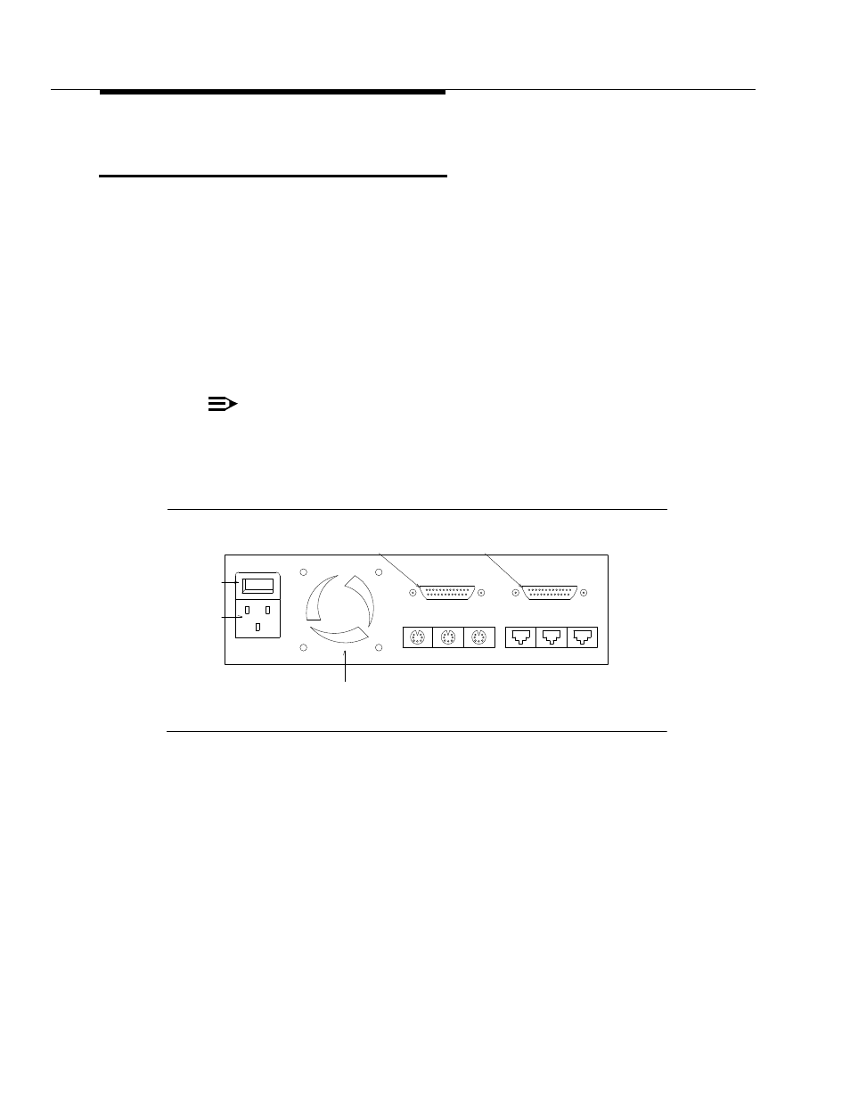
1. Connect one end of the Null cable to the 25-pin Link B on the SID, shown
2. Connect Port 0 of the Y-cable to the free end of the Null cable.
NOTE
:
Port 1 on the Y-cable is not used for any connections with this
integration.
Proceed to the next section.
Figure 4-3.
Back View of the SID
25 Pin
25 Pin
(Fan Outlet)
Link A
Link B
Diag
Net B
Net A
Line B
Line A
Modem
115-230V AC
50/60 Hz
Power
Cord
Outlet
(Male)
Power
Switch