Important, Serial port connector: com2 – MSI 3200 Network User Manual
Page 32
2-16
MS-91A2 Server Board
Fan Power Connector: CPU_FAN1, SYS_FAN1/2, FRONT_FAN1
The fan power connectors support system cooling fan with +12V. W hen connecting
the wire to the connectors, always note that the red wire is the positive and should
be connected to the +12V; the black wire is Ground and should be connected to GND.
If the mainboard has a System Hardware Monitor chipset onboard, you must use a
specially designed fan with speed sensor to take advantage of the CPU fan control.
Important
1. Please refer to the recommended CPU fans at processor’s official website
or consult the vendors for proper CPU cooling fan.
2. Users are suggested to enter the BIOS Setup Utility to set up the Smart Fan
Control function.
CPU_FAN1
S
E
N
S
O
R
+
1
2
V
G
N
D
C
O
N
T
R
O
L
SYS_FAN1/2,
FRONT_FAN1
S
E
N
S
O
R
+
1
2
V
G
N
D
C
O
N
T
R
O
L
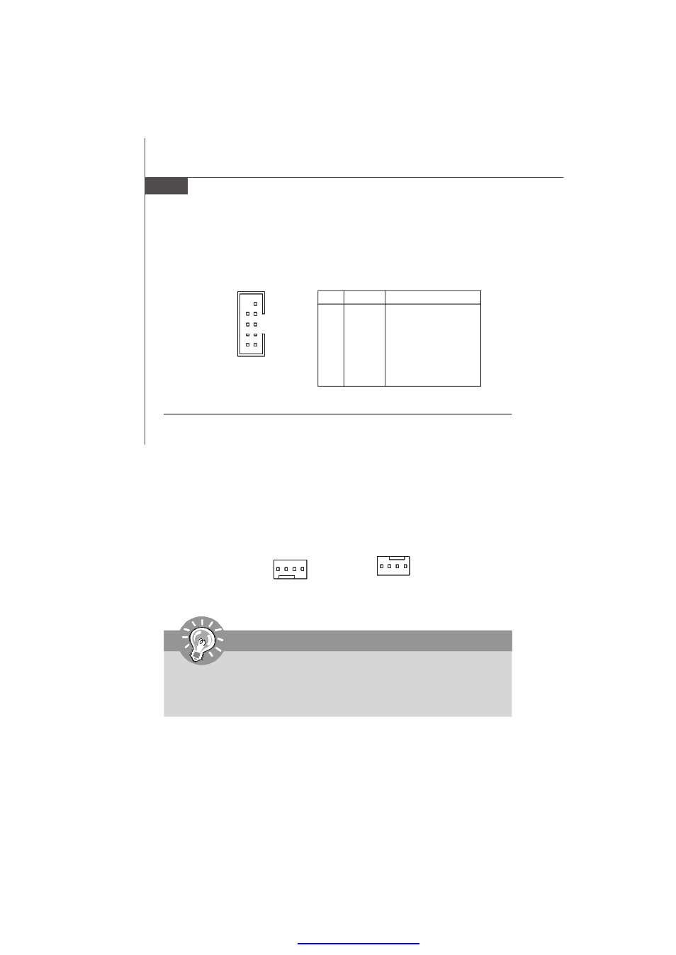
Serial Port Connector: COM2
This connector is a 16550A high speed communications port that sends/receives 16
bytes FIFOs. You can attach a serial device to it through the optional serial port
bracket.
PIN
SIGNAL
DESCRIPTION
1
DCD
Data Carry Detect
2
SIN
Serial In or Receive Data
3
SOUT
Serial Out or Transmit Data
4
DTR
Data Terminal Ready
5
GND
Ground
6
DSR
Data Set Ready
7
RTS
Request To Send
8
CTS
Clear To Send
9
VCC_COM
Power Source
Pin Definition
COM 2
1
9
2
8
PDF created with pdfFactory Pro trial versi