Howard Substation Transformers User Manual
Page 8
Copyright © 2013 Howard Industries, Inc.
Howard Industries, Inc.
Laurel, MS 39440
www.howardtransformers.com
Document No. 2.4.18
Revision: 2
Issued: October, 2013
8
Medium Power Substation Transformers
34-10
GAUGES
All gauges are dial-type and are
located for convenient viewing at
ground level (Figure 18).
Figure 18:
Gauges
Fluid temperature and winding
temperature gauges have resettable
maximum temperature drag hands.
ELECTRONIC MONITORING
Various sophisticated electronic
monitoring systems are available as
options, including those that monitor
oil temperature, winding temperature,
pressure, moisture, gases, apparent
charge, arrester surge count, and
leakage current. Contact the factory
for these and other monitoring
systems that may be available.
CONTROL CABINET
The control cabinet provides a
weatherproof enclosure for accessory
items such as fan controls, OLTC
controls, and terminal blocks for
customer connections (Figure 19).
The cabinet is mounted on the side of
the transformer tank. Access to the
cabinet is protected by a hinged door
with three-point latch and padlock
provisions. The cabinet interior is
painted white to improve visibility and
is equipped with a work light and
accessory power outlet.
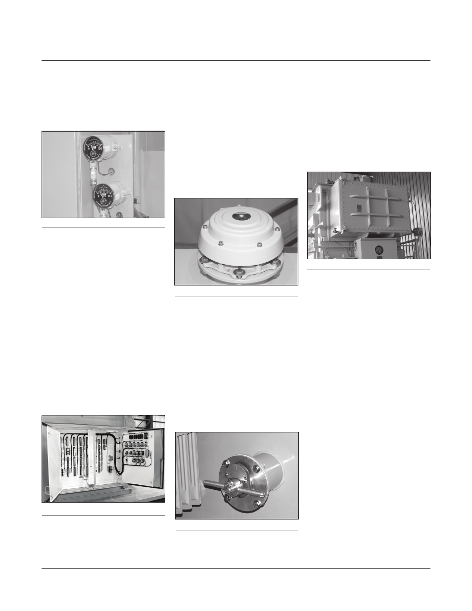
PRESSURE RELIEF DEVICE
A cover-mounted automatic pressure-
relief device is provided to vent
excessive pressure that might build
up gradually during extreme over-
loads or fault conditions (Figure 20).
The standard device has a 6” throat
and a cracking pressure of 10 psi.
Devices with other pressure and flow
characteristics are available with
nonstandard operating characteris-
tics. Options include alarm contacts,
indicating flag, and discharge diverter.
DE-ENERGIZED TAP CHANGER
A de-energized tap changer can be
provided to adjust the transformer
voltage ratio to meet system require-
ments. An external operating handle
is mounted on one end of the trans-
former near ground level (Figure 21).
The handle can be locked in any
switch position and has provisions for
a padlock.
ON-LOAD TAP CHANGER
A three-phase on-load tap changer
(OLTC) provides automatic voltage
regulation in an energized trans-
former while serving load (Figure 22).
OLTC’s typically operate over a range
of thirty-two 5/8% voltage steps,
sixteen above and sixteen below
rated secondary voltage. The total
tap range is typically 20% (10% above
and 10% below rated secondary
voltage). Standard OLTC’s provided
on Howard transformers use vacuum
interrupter technology manufactured
by Reinhausen or ABB.
The OLTC switch mechanism is sealed
in an oil-filled enclosure welded to
one end of the main transformer
tank. A motor drive and switch
position indicator are housed in a
weatherproof cabinet mounted below
the switch mechanism. A crank lever
is provided to operate the tap changer
manually.
OLTC control panels are housed
in the control cabinet (Figure 23).
A variety of microprocessor-based
controls are available, including those
manufactured by Beckwith, ICMI, and
Reinhausen. In addition to the
automatic regulation of secondary
voltage, control systems can also be
equipped to provide communication,
data storage, and power quality
analysis. All controls are provided with
manual override capability.
Figure 19:
Control cabinet
Figure 20:
Pressure relief device
Figure 21:
DETC handle
Figure 22:
On-load tap changer