Howard Substation Transformers User Manual
Page 4
Copyright © 2013 Howard Industries, Inc.
Howard Industries, Inc.
Laurel, MS 39440
www.howardtransformers.com
Document No. 2.4.18
Revision: 2
Issued: October, 2013
4
Medium Power Substation Transformers
34-10
ELECTRICAL CIRCUIT
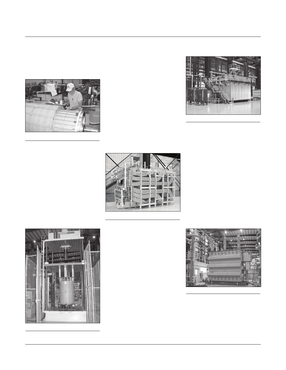
Windings are cylindrical construction,
with concentric windings separated by
axial oil ducts (Figure 8).
Figure 8:
Coil winding
The type of winding used depends
on the voltage rating. Low-voltage
windings are helical type, medium-
voltage windings are continuous disc
type, and high-voltage windings are
shielded disc. Conductor material
is C11000 grade copper, tough
pitch cast, with ASTM edge radius,
and custom tempered per design
requirements. The conductor is
insulated with thermally upgraded
crepe paper tape, wrapped in multiple
layers. Rectangular conductor or
continuously-transposed cable
(CTC) is used according to design
requirements.
Finished coils are oven dried and
accurately sized in a computer-
controlled hydraulic press (Figure 9).
Coil sizing establishes the coil’s
electrical length at a specified
pressure. Sizing pressure is
determined by design engineering,
and is sufficient to contain axial short-
circuit forces that would be generated
during throughfault conditions.
ASSEMBLY
After the coil sizing process is
completed, core and coils are
assembled together in a heavy-duty
clamping structure that produces
a rugged, stable assembly, yet
minimizes mechanical stress in the
core (Figure 10).
High-density laminated pressure rings
transmit uniform clamping pressure
to each coil. The lead structure is
designed to provide generous
dielectric clearance and to resist
the lead forces generated by system
faults. Leads are secured using
either pressboard or kiln-dried maple
braces.
COIL DRYING
Core and coils are dried and oil
impregnated in a Micafil automated
vapor-phase system (Figure 11).
Proper dryness is critical to maintain
the integrity and life of the insulation
system. The Micafil process
automatically monitors and controls
moisture extraction in an oxygen-free
environment, producing an extremely
dry insulation system. During the final
phase of the Micafil process, the
drying chamber is flooded with
transformer oil to impregnate the
insulation system fully.
FACTORY TESTING
In addition to numerous quality
inspections throughout the manu-
facturing process, final tests are
conducted on the completed
transformer to ensure proper
function of all systems. All tests
are conducted in accordance with
applicable industry standards. Test
equipment is state-of-the-art and
capable of extremely accurate and
reliable test measurements, meeting
all the industry loss measurement
standards. (Figure 12). All test
systems are calibrated regularly
according to industry standards.
Figure 9:
Coil sizing press
Figure 10:
Core coil unit
Figure 12:
Electrical test station
Figure 11:
Micafil vapor phase system