Howard Substation Transformers User Manual
Page 7
Copyright © 2013 Howard Industries, Inc.
Howard Industries, Inc.
Laurel, MS 39440
www.howardtransformers.com
Document No. 2.4.18
Revision: 2
Issued: October, 2013
7
Medium Power Substation Transformers
34-10
class) (Figure 13).
Sealed motor-driven fans are
mounted on radiators to provide
increased air flow. Fan operation
may be manual or may be controlled
automatically by temperature sensors
mounted inside the transformer. Fans
are connected to a weatherproof
control box with weatherproof cable
and a separable connector.
A second stage of forced-air cooling
may be used (ONAF/ONAF class) to
provide a further increase in load
capacity beyond that provided by
single-stage forced-air cooling.
Stages one and two are operated
automatically by heat sensors
mounted inside the transformer tank
and a control panel mounted inside
the control cabinet.
FLUID PRESERVATION
A sealed-tank fluid preservation
system is standard on all Howard
medium power transformers. The
interior of the tank is sealed from the
ambient atmosphere, such that the
gas-plus-oil volume remains constant
throughout the range of normal
operating temperatures. An automatic
pressure relief device is provided to
vent excessive pressure that might
build up gradually during extreme
overloads or fault conditions. A
pressure/vacuum gauge is provided
to measure internal pressure. Prior to
shipping the gas space is pressurized
with a dry air or nitrogen blanket.
INERT GAS SYSTEM
An optional nitrogen inert-gas system
provides a constant nitrogen
atmosphere in the gas space of the
transformer (Figure 14). The
nitrogen blanket protects the
transformer fluid from deterioration
that could occur from exposure to
moisture or oxygen. Main system
components include a nitrogen
cylinder, pressure regulators, valves,
and gauges. The system also includes
provisions for various pressure
alarms. A lockable weatherproof
enclosure protects the system.
BUSHINGS
Standard bushings are oil-filled
condenser-type with porcelain
housings (Figure 15).
All bushings meet the requirements
of the IEEE C57.19 series of
standards.
CURRENT TRANSFORMERS
Current transformers (CTs) are
bushing-mounted in the main tank
interior (Figure 16). All CTs meet
the requirements of the IEEE C57.13
series of standards.
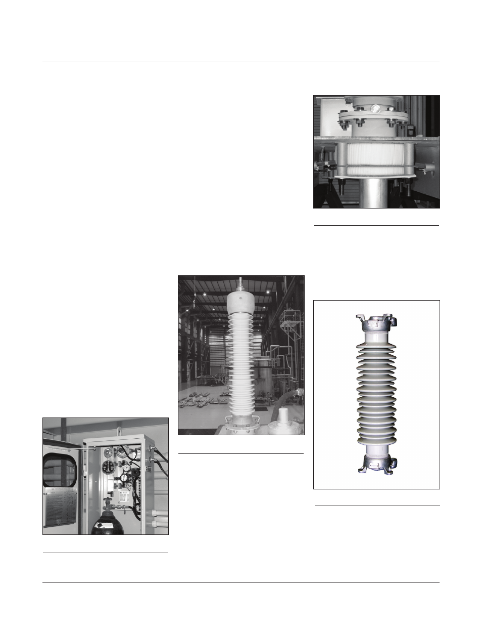
SURGE ARRESTERS
Surge arresters are porcelain or
polymer housed, gapless metal-
oxide-varister (MOV) type (Figure
17), externally mounted on heavy
steel brackets. All arresters meet the
requirements of IEEE C62.11.
Figure 14:
Nitrogen system
Figure 15:
High voltage bushing
Figure 16:
CTs mounted under cover
Figure 17:
Lightning arrester