Design and manufacturing processes – Howard Substation Transformers User Manual
Page 3
Copyright © 2013 Howard Industries, Inc.
Howard Industries, Inc.
Laurel, MS 39440
www.howardtransformers.com
Document No. 2.4.18
Revision: 2
Issued: October, 2013
3
Medium Power Substation Transformers
34-10
TRANSFORMER DESIGN
Howard’s design philosophy employs
technology in ways that provide a
cost-competitive transformer built
with conservative design margins, a
thorough verification of designs using
the latest computer analysis tools,
and automation of the design process
to reduce cycle time and eliminate
human error.
Our experienced mechanical
designers employ the latest available
computer-based design tools, such as
parametric 3D computer-aided design
systems (Figure 4) for both internal
and external layouts. The Anderson
2D finite element analysis program,
the Ansoft Maxwell 2D electrostatic
and magnostatic field analysis
program, 3D ALGORE mechanical
analysis program, and others are
used in the determination of electrical
and mechanical design margins.
The design verification process
includes:
• Validation of transient voltage
response
• Validation of short-circuit strength
• Analysis of eddy losses and hotspot
calculations
• Validation of insulation design
• Verification of loading beyond
nameplate capacity
• In-rush current analysis
• Over-voltage analysis
Howard substation transformers are
designed with conservative
mechanical and electrical margins to
withstand the harsh environments
encountered in today’s power delivery
systems. Exceptional short-circuit and
impulse strengths are hallmarks of
the Howard design. All transformer
designs are optimized to satisfy our
customers’ total cost of ownership
requirements.
General industry standards applicable
to Howard substation transformer
designs include IEEE C57.12.00
(Standard General Requirements for
Liquid-Immersed Distribution, Power,
and Regulating Transformers), IEEE
C57.12.90 (Standard Test Code for
Liquid-Immersed Distribution, Power
and Regulating Transformers and
Guide for Short Circuit Testing of
Distribution and Power Transformers),
IEEE C57.93 (Guide for Installation
of Liquid-Immersed Power Trans-
formers), IEEE C57.98 (Guide for
Transformer Impulse Tests), and IEEE
C57.100 (Standard Test Procedure for
Thermal Evaluation of Oil Immersed
Distribution Transformers).
MAGNETIC CIRCUIT
Howard medium power substation
transformers employ core-type
construction and are designed with
an optimized cruciform configuration
with step-lap joints to provide
excellent mechanical strength and
magnetic performance. Core designs
use regular grain-oriented steels
which have been precision slit to
width and stress-relieved by our
supplier. Core laminations are
precisely cut to length and mitered on
a computer-controlled Georg cutting
line (Figure 5).
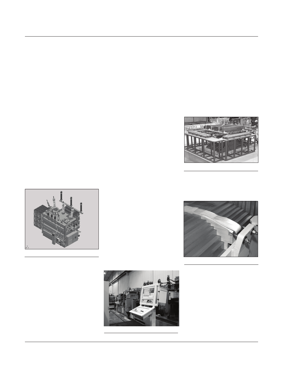
Core laminations are carefully
stacked on precision hydraulic lift
tables to prevent misalignment when
up-righting (Figure 6).
Cores are securely banded and
clamped with tie plates to ensure
stability and minimize stress on the
core. Core support blocks (Figure 7)
and cooling ducts are used to provide
uniform pressure across the
lamination surface. The top and
bottom core clamps are held together
by steel lock plates configured to
contain mechanical short-circuit
forces and modified as necessary
for leakage flux to limit excessive hot
spots.
DESIGN AND MANUFACTURING PROCESSES
Figure 4:
Image of 3D CAD model
Figure 7:
Core support blocks
Figure 6:
Core Stacking Table
Figure 5: Georg core cutter