Dai initialization – Cirrus Logic AN199 User Manual
Page 2
2
Copyright 2001 Cirrus Logic (All Rights Reserved)
AN199Rev1
AN199
DAI Initialization
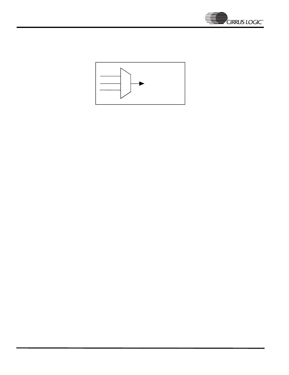
The DAI machine shares the output pins with two other devices via an internal MUX. The DAI machine is selected,
output pins are assigned to the machine, then enabled before exiting the routine. See the figure below.
• To program the MUX shown above for DAI control, set bit 3 in the System Control Register 3 (SYSCON3).
• If an external clock will generate *MCLK, enable clock.
• The DAI Control Register (DAIR) is programmed with the lower 2 bytes 0404 required. The Right Channel
Transmit FIFO Interrupt Mask (RTCM) is enabled. This is the only interrupt which will call the FIQ for
processing music. External clock source (ECS) bit should also be enabled if external MCLK generator is
used.
• Clear DAI Status Register (DAISR) of any overrun or underrun bits. A write of 0xFFFFFFFF to this location
is sufficient.
• Turn on the DAI by asserting pin 9 of SYSCON3.
• Enable the left and right channel FIFOs in the DAI Data Register 2 (DAIDR2). This will require checking the
DAI status register for each left and right channel enable to make sure the FIFO bit is set.
• Unmask the DAI Interrupt at the DAIINT register. Once unmasked, the DAI FIQ will assert since the RTCM
is already half empty or more and you will immediately enter the FIQ Handler. There is no music to play so
the handler must process the first entry with no data (refer to the FIQ Handler discussion).
Note:
*The designer has the option of using an internally generated MCLK or an external MCLK for synchronization with the external
CODECs.
DAI
CODEC
SSI2
SCLK
MCLK
LRCLK
SDIN
SDOUT