Capacitor size on reference voltage pin(s), Figure 5. cs5381 thd+n vs. frequency, An234 – Cirrus Logic AN234 User Manual
Page 6
AN234
6
9. Capacitor Size on Reference Voltage Pin(s)
The CS5381 and the AK5394A both require external capacitance on the internal reference voltage pin(s).
On the CS5381, the internal reference voltage is output on FILT+ (pin 24). The AK5394A has four such
pins, VREFL+, VREFL-, VREFR-, and VREFR+ (pins 1, 2, 27, and 28 respectively). Each of these pins
require a large capacitor for noise decoupling. Please refer to Figure 12 of the AK5394A datasheet (dated
January, 2002) for a plot of distortion versus frequency with various capacitor values on these reference
pins.
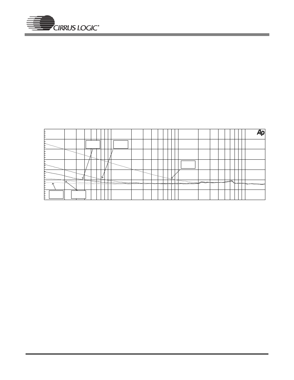
For comparison, the same plot has been generated using the CS5381, as can be seen in Figure 5. Please
note that the CS5381 requires ONE such capacitor, while the AK5394A requires FOUR such capacitors.
Figure 5. CS5381 THD+N vs. Frequency
A comparison between Figure 12 of the AK5394A datasheet and the above plot of the CS5381 reveals
that the CS5381 has better low frequency distortion performance for a given capacitor value, and requires
only one capacitor as opposed to the four that are required for the AK5394A.
CS5381 THD+N vs Frequency
-1dBFS Input
-130
-60
-120
-110
-100
-90
-80
-70
d
B
F
S
10
20k
20
50
100
200
500
1k
2k
5k
10k
Hz
10
µ
F
100
µ
F
220
µ
F
470
µ
F
1000
µ
F