Pin compatibility, Offset calibration, 1 cs5381 – Cirrus Logic AN234 User Manual
Page 3: An234
AN234
3
3. Pin Compatibility
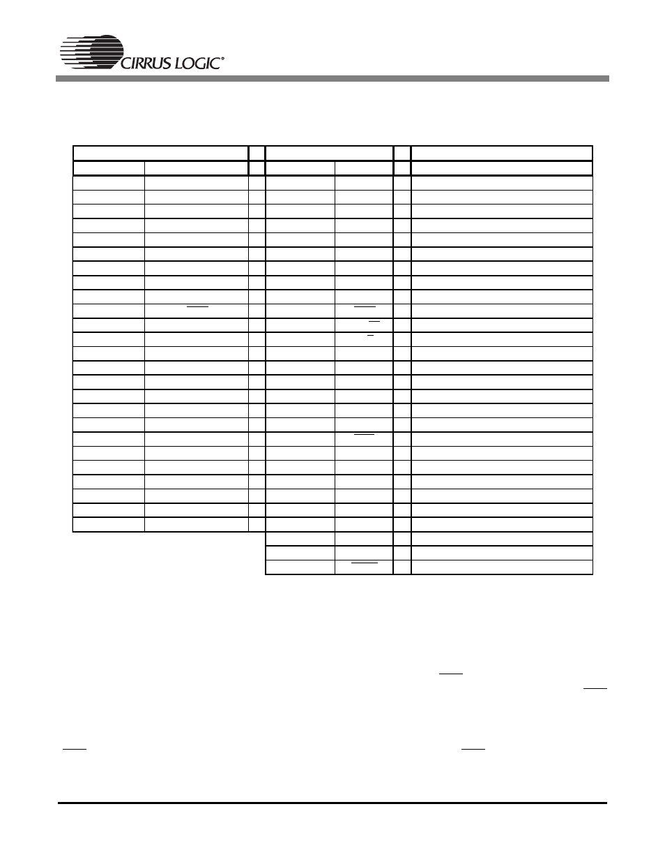
Table 1 shows the pins of the AK5394A and the corresponding pins of the CS5381. Please note that the
AK5394A has 28 pins, and the CS5381 has 24 pins.
Table 2. Pin Compatibility Between AK5394A and CS5381
4. Offset Calibration
The CS5381, and AK5394A all have offset calibration capability. However, the calibration process varies
slightly between the AK5394A and the CS5381.
4.1
CS5381
The CS5381 implements a high pass filter that can be controlled via the HPF pin (pin 11). The high pass
filter continuously subtracts a measure of the DC offset from the output of the decimation filter. If the HPF
pin is taken high during normal operation, the current value of the DC offset register is frozen and this DC
offset will continue to be subtracted from the conversion result.
A system calibration can then be performed by first running the CS5381 with the high pass filter enabled
(HPF = LOW) until the filter settles. At this point, disable the high pass filter (HPF = HI), thereby freezing
the stored DC offset.
AK5394A
CS5381
Description
Pin Number
Pin Name
Pin Number
Pin Name
1, 28
VREFL+, VREFR+
24
FILT+
Positive reference voltage
2, 27
VREFL-, VREFR-
23
REFGND
Ground reference
3, 26
VCOML, VCOMR
22
VQ
Internal quiescent reference voltage
4
AINL+
16
AINL+
Differential Left Channel Input
5
AINL-
17
AINL-
Differential Left Channel Input
6
ZCAL
-
-
Zero Calibration Control
7
VD
6
VD
Digital power
8
DGND
7
GND
Ground reference
9
CAL
-
-
Calibration Active Signal
10
RST
1
RST
Reset
11
SMODE2
12
I2S/LJ
Digital Interface Format Select
12
SMODE1
2
M/S
Master/Slave Mode Select
13
LRCK
3
LRCK
Left right clock
14
SCLK
4
SCLK
Serial clock
15
SDATA
9
SDOUT
Serial data
16
FSYNC
-
-
Frame Synchronization Signal
17
MCLK
5
MCLK
Master clock
18
DFS0
13
M0
Mode selection
19
HPFE
11
HPF
High Pass Filter Enable
20
DFS1
14
M1
Mode selection
21
BGND
-
-
Substrate Ground
22
AGND
18
GND
Ground reference
23
VA
19
VA
Analog power
24
AINR-
20
AINR-
Differential Right Channel Input
25
AINR+
21
AINR+
Differential Right Channel Input
8
VL
Logic Power
10
MDIV
MCLK divider
15
OVFL
Overflow