Cirrus Logic CDB44800 User Manual
Features, Description, Eight output channels
Copyright
© Cirrus Logic, Inc. 2004
(All Rights Reserved)
Cirrus Logic, Inc.
www.cirrus.com
CDB44800
Evaluation Board For CS44800
Features
z
Eight Output Channels
z
Configurable for full-bridge or half-bridge
operation, allowing evaluation of different output
power levels and BOM options.
z
Single Positive Voltage Supply for Amplified
Audio Outputs
z
CS4461 for Power Supply Rejection Feedback
z
Header for External Serial Audio I/O
z
Adjustable Power Supplies for Easy
Configuration
z
Software provided to configure the board.
z
Demonstrates recommended layout and
grounding arrangements.
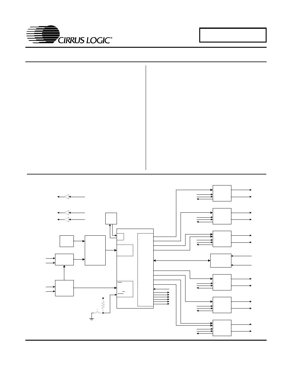
Description
The CDB44800 demonstration board is an excellent
means for evaluating the CS44800 eight-channel Class-
D PWM modulator. Evaluation requires a digital audio
signal source, analog audio analyzer, and power
supplies.
Clocks and data can be provided to the CS44800 by the
CS8416 S/PDIF receiver or by an I/O header. PWM out-
put from the CS44800 is amplified using the Philips
TDA8939 power stage. The CS4461 is used for power
supply rejection. A line out and headphone driver are
provided as well. A comprehensive GUI provides control
over the functions of the CS44800, CS4461, CS8416,
and Philips TDA8939.
ORDERING INFORMATION
CDB44800
Evaluation Board
I
DAI_MCLK
DAI_SCLK
DAI_LRCK
DAI_SDIN[1:4]
MUTE
RST
SCL/CCLK
SDA/CDOUT
VLS
VLC
AD1/CDIN
AD0/CS
XTI
XTO
VDX
PWMOUTA1+
PWMOUTA1-
PWMOUTB1+
PWMOUTB1-
VDP
PWMOUTA2+
PWMOUTA2-
PWMOUTB2+
PWMOUTB2-
PWMOUTA3+
PWMOUTA3-
PWMOUTB3+
PWMOUTB3-
PWMOUTA4+
PWMOUTA4-
PWMOUTB4+
PWMOUTB4-
GPIO0
GPIO1
GPIO2
GPIO3
GPIO4
GPIO5
GPIO6
PSR_MCLK
PSR_SYNC
PSR_DATA
PSR_EN
PSR_RESET
CS44800
RXP0
RXP1
RMCK
SCLK
LRCK
SDOUT
CS8416
RCA
OPT
MCK
SCLK
LRCK
SDIN[1:4]
PCM
Header
Osc /
Fndmntl /
3rd/5th /
7th
Clock
Inputs
MCLK_A
MCLK_B
MCK
SCLK
LRCK
SDIN[1:4]
2:1 MUXes
SCLK_A
SCLK_B
LRCK_A
LRCK_B
SDIN[1:4]_A
SDIN[1:4]_B
Control
Port
VLC
PWR_UP_HB
ENABLE1
DIAG
ENABLE2
PWR_UP_FB
ENABLE3
ENABLE4
Line Out
PWMOUTB3+
HP Out
PWMOUTA1+
PWMOUTB1+
Serial
USB
IN1±
IN2±
OUT1
OUT2
TDA8939
PWRUP
ENABLE
DIAG
PWR_UP_FB
ENABLE3
DIAG
IN1±
IN2±
OUT1
OUT2
TDA8939
PWRUP
ENABLE
DIAG
PWR_UP_FB
ENABLE3
DIAG
PSR_MCLK
AIN+
AIN-
CS4461
PSR_SYNC
PSR_RESET
PSR_DATA
PSR_EN
High Voltage
Power Suppy
(20 V to 50 V)
IN1±
IN2±
OUT1
OUT2
TDA8939
PWRUP
ENABLE
DIAG
PWR_UP_FB
ENABLE4
DIAG
IN1±
IN2±
OUT1
OUT2
TDA8939
PWRUP
ENABLE
DIAG
PWR_UP_FB
ENABLE4
DIAG
IN1±
IN2±
OUT1
OUT2
TDA8939
PWRUP
ENABLE
DIAG
PWR_UP_HB
ENABLE2
DIAG
IN1±
IN2±
OUT1
OUT2
TDA8939
PWRUP
ENABLE
DIAG
PWR_UP_HB
ENABLE1
DIAG
CH 3 (Half Bridge)
CH 1+ (Full Bridge)
CH 1- (Full Bridge)
CH 2+ (Full Bridge)
CH 2- (Full Bridge)
CH 4 (Half Bridge)
CH 7 (Half Bridge)
CH 5+ (Full Bridge)
CH 5- (Full Bridge)
CH 6+ (Full Bridge)
CH 6- (Full Bridge)
CH 8 (Half Bridge)
OCT ‘04
DS632DB2