Cirrus Logic CDB4398 User Manual
Cirrus Logic Hardware
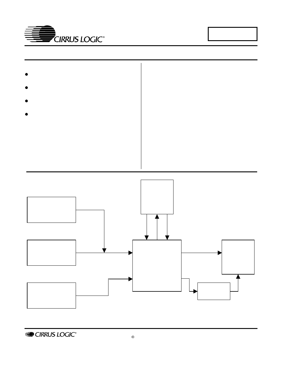
Table of contents
Document Outline
- Features
- Description
- 1. CS4398 Digital to Analog Converter
- 2. CS8414 Digital Audio Receiver
- 3. Input/Output for Clocks and Data
- 4. Power Supply Circuitry
- 5. Grounding and Power Supply Decoupling
- 6. Control port Software
- 7. DSD Operation
- 8. Analog output filterING
- 9. Errata
- CDB4398 Revision B.0
- Figure 1. System Block Diagram and Signal Flow
- Figure 2. CS4398
- Figure 3. CS8414 Digital Audio Receiver
- Figure 4. PCM and DSD Input Headers
- Figure 5. Control Port Interface
- Figure 6. Channel A Outputs and Mute
- Figure 7. Channel B Outputs and Mute
- Figure 8. Power Supply Connections
- Figure 9. Silkscreen Top
- Figure 10. Top Side
- Figure 11. Bottom Side
- CDB4398 Revision B.0