Control port software, Dsd operation, Analog output filtering – Cirrus Logic CDB4398 User Manual
Page 4: Cdb4398
CDB4398
4
6. CONTROL PORT SOFTWARE
The CDB4398 is shipped with Windows 95/98/ME based software as well as Windows NT/2000/XP driv-
ers for interfacing with the CS4398 control port via the DB25 connector, J21. The software can be used to
communicate with the CS4398 in either SPI
or I
2
C mode. See the readme.txt for more information.
7. DSD OPERATION
The CDB4398 supports Direct Stream Digital (DSD) operation through the header for external clocks and
data, J14. The CS4398 must be configured for the DSD mode and header J11 should be set to “external”.
See Table 2 for more information.
8. ANALOG OUTPUT FILTERING
The analog output on the CDB4398 has been designed to add flexibility when evaluating the CS4398. Two
output filter options are offered a 2-pole butterworth 50kHz low-pass filter with single ended outputs and
a 3-pole filter with XLR outputs.
The 2-pole filter (RCA) is designed to have the in-band impedance matched between the positive and neg-
ative legs. It also provides a balanced to single ended conversion for standard un-balanced outputs.
The 3-pole filter (XLR) is designed to have extremely low self noise and distortion in order to evaluate the
full performance of the CS4398.
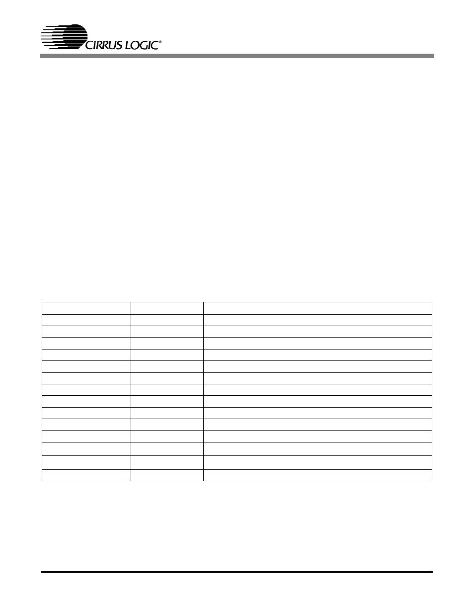
Table 1. System Connections
CONNECTOR
INPUT/OUTPUT
SIGNAL PRESENT
+5V
Input
+ 5 Volt power
VD
Input
+ 3.3 to +5V power for the CS4398 digital supply
VLS
Input
+ 1.8 to +5V power for the CS4398 serial interface
VLC
Input
+ 1.8 to +5V power for the CS4398 control interface
J9
Input
-18 to -12V negative supply for the op-amps
J10
Input
+12 to +18V positive supply for the op-amps
GND
Input
Ground connection from power supply
SPDIF INPUT - J17
Input
Digital audio interface input via coax
SPDIF INPUT - OPTO-1
Input
Digital audio interface input via optical
PCM INPUT - J12
Input
Input for master, serial, left/right clocks and serial data
DSD INPUT - J14
Input
Input for DSD data and clock
PC Port
Input/Output
Parallel connection to PC for SPI / I
2
C control port signals
EXT CTRL I/O
Input/Output
I/O for SPI / I
2
C control port signals
OUTA and OUTB
Output
RCA and XLR line level analog outputs