Cirrus Logic CDB4398 User Manual
Cirrus Logic Hardware
1
Copyright
Cirrus Logic, Inc. 2003
(All Rights Reserved)
http://www.cirrus.com
CDB4398
Evaluation Board for CS4398
Features
Demonstrates recommended layout and
grounding arrangements
CS8414 receives S/PDIF, & EIAJ-340
compatible digital audio
Headers for external audio input for either
PCM or DSD
Requires only a digital signal source and
power supplies for a complete Digital-to-
Analog-Converter system
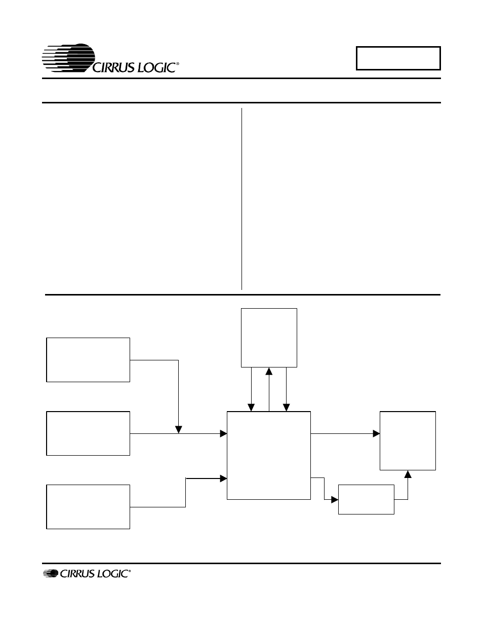
Description
The CDB4398 evaluation board is an excellent means
for quickly evaluating the CS4398 24-bit, high perfor-
mance stereo D/A converter. Evaluation requires an
analog signal analyzer, a digital signal source, a PC for
controlling the CS4398 (stand alone operation is also
available) and a power supply. Analog line level outputs
are provided via RCA phono jacks and balanced XLR.
The CS8414 digital audio receiver I.C. provides the sys-
tem timing necessary to operate the Digital-to-Analog
converter and will accept S/PDIF, and EIAJ-340 compat-
ible audio data. The evaluation board may also be
configured to accept external timing and data signals for
operation in a user application during system
development.
ORDERING INFORMATION
CDB4398 Evaluation Board
CS4398
Analog
Outputs
MUTE
Control
Port
Inputs for Clocks
and Data
Inputs for DSD
Data and Clock
CS8414
Digital Audio
Interface
JUL ‘03
DS568DB1
Document Outline
- Features
- Description
- 1. CS4398 Digital to Analog Converter
- 2. CS8414 Digital Audio Receiver
- 3. Input/Output for Clocks and Data
- 4. Power Supply Circuitry
- 5. Grounding and Power Supply Decoupling
- 6. Control port Software
- 7. DSD Operation
- 8. Analog output filterING
- 9. Errata
- CDB4398 Revision B.0
- Figure 1. System Block Diagram and Signal Flow
- Figure 2. CS4398
- Figure 3. CS8414 Digital Audio Receiver
- Figure 4. PCM and DSD Input Headers
- Figure 5. Control Port Interface
- Figure 6. Channel A Outputs and Mute
- Figure 7. Channel B Outputs and Mute
- Figure 8. Power Supply Connections
- Figure 9. Silkscreen Top
- Figure 10. Top Side
- Figure 11. Bottom Side
- CDB4398 Revision B.0