9 using dsd mode, 10 mute control, 9 using dsd mode 3.10 mute control – Cirrus Logic CS4392 User Manual
Page 13: Cs4392
CS4392
DS459PP3
13
3.9
Using DSD mode
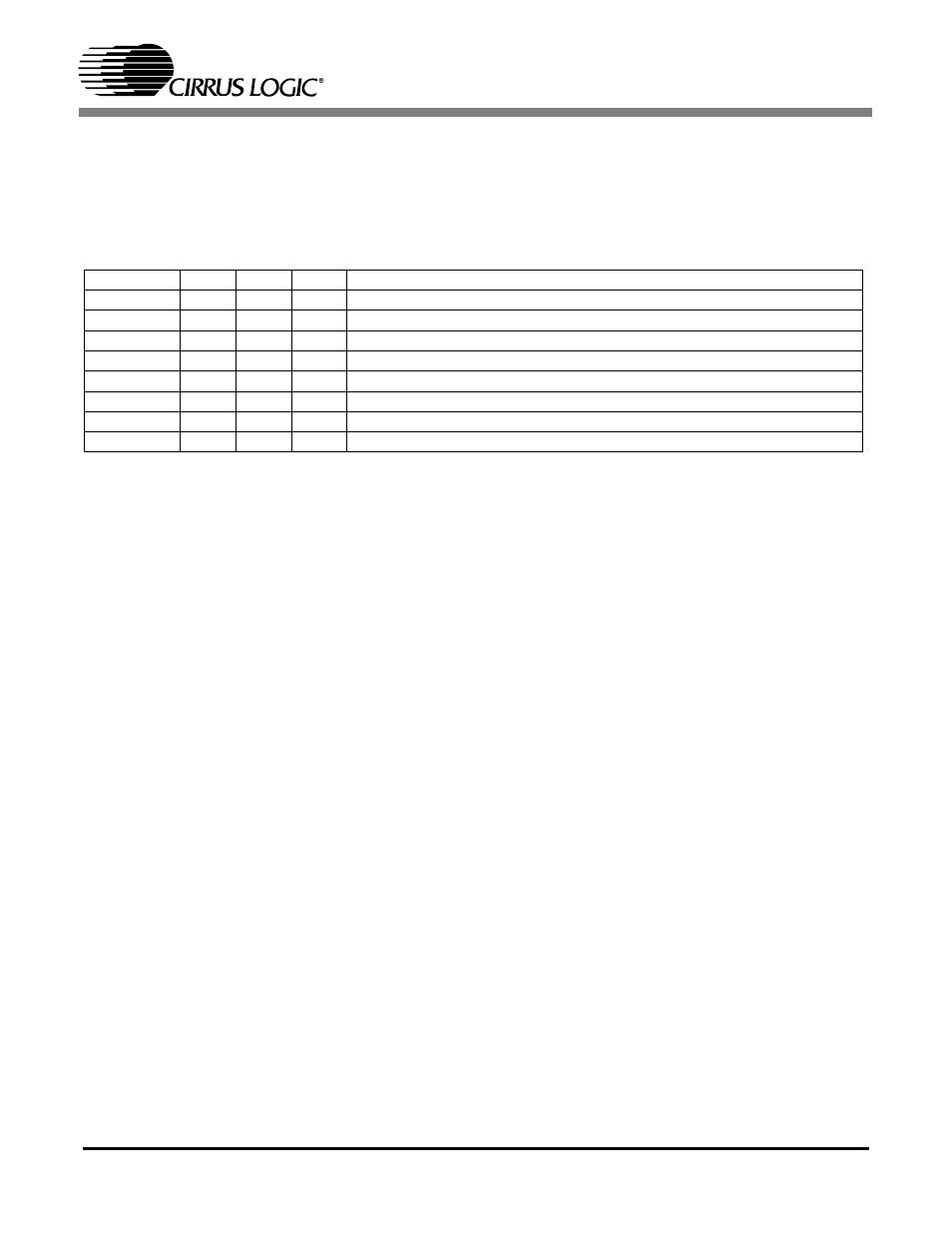
In stand-alone mode, DSD operation is selected by holding DSD_EN(LRCK) high and applying the DSD
data and clocks to the appropriate pins. The M2:0 pins set the expected DSD rate and MCLK ratio.
In control-port mode the FM bits set the device into DSD mode (DSD_EN pin is not required to be held
high). The DIF register then controls the expected DSD rate and MCLK ratio.
3.10 Mute Control
The Mute Control pins go high during power-up initialization, reset, or if the Master Clock to Left Right
Clock ratio is incorrect. These pins will also go high following the reception of 8192 consecutive audio
samples of static 0 or -1 on both the left and right channels. A single sample of non-zero data on either
channel will cause the Mute Control pins to go low. These pins are intended to be used as control for an
external mute circuit in order to add off-chip mute capability.
Use of the Mute Control function is not mandatory but recommended for designs requiring the absolute
minimum in extraneous clicks and pops. Also, use of the Mute Control function can enable the system de-
signer to achieve idle channel noise/signal-to-noise ratios which are only limited by the external mute cir-
cuit. See the CDB4392 data sheet for a suggested mute circuit.
DSD_Mode
M2
M1
M0
DESCRIPTION
1
0
0
0
64x oversampled DSD data with a 4x MCLK to DSD data rate
1
0
0
1
64x oversampled DSD data with a 6x MCLK to DSD data rate
1
0
1
0
64x oversampled DSD data with a 8x MCLK to DSD data rate
1
0
1
1
64x oversampled DSD data with a 12x MCLK to DSD data rate
1
1
0
0
128x oversampled DSD data with a 2x MCLK to DSD data rate
1
1
0
1
128x oversampled DSD data with a 3x MCLK to DSD data rate
1
1
1
0
128x oversampled DSD data with a 4x MCLK to DSD data rate
1
1
1
1
128x oversampled DSD data with a 6x MCLK to DSD data rate
Table 7. Direct Stream Digital (DSD), Stand-Alone Mode Options