6 digital interface format, Figure 5. format 1, i2s up to 24-bit data, Cs4392 – Cirrus Logic CS4392 User Manual
Page 11
CS4392
DS459PP3
11
3.6
Digital Interface Format
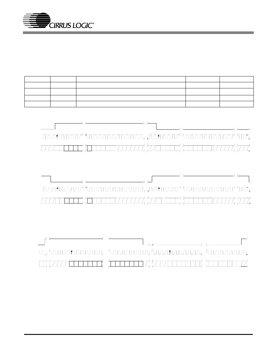
The device will accept audio samples in several digital interface formats as illustrated in Tables 5 and 8.
The desired format is selected via the M0 and M1 pins for stand alone mode, and through the DIF2:0 bits
in the control port. For an illustration of the required relationship between the Left/Right Clock, Serial
Clock and Serial Audio Data, see Figures 4-6.
M1
M0
DESCRIPTION
FORMAT
FIGURE
0
0
Left Justified, up to 24-bit data
0
0
1
I
2
S, up to 24-bit data
1
1
0
Right Justified, 16-bit Data
2
1
1
Right Justified, 24-bit Data
3
Table 5. Digital Interface Format, Stand-Alone Mode Options
Figure 4. Format 0, Left Justified up to 24-Bit Data
L R C K
S C L K
L e ft C h a n n e l
R ig h t C h a n n e l
S D A T A
+3 +2 +1 LS B
+5 +4
M SB -1 -2 -3 -4 -5
+3 +2 +1 LS B
+5 +4
M S B -1 -2 -3 -4
Figure 5. Format 1, I
2
S up to 24-Bit Data
L R C K
S C L K
L e ft C h a n n e l
R ig h t C h a n n e l
S D A T A
+3 +2 +1 LSB
+5 +4
MSB -1 -2 -3 -4 -5
+3 +2 +1 LSB
+5 +4
M SB -1 -2 -3 -4
LR C K
S C LK
L e ft C h a n ne l
S D A TA
+5 +4 +3 +2 +1
LSB
MSB
-1 -2 -3 -4 -5
3 2 c lo ck s
R ig h t C h a n n e l
LSB
+5 +4 +3 +2 +1
LSB
MSB
-1
-2 -3 -4 -5
+6
-6
+6
-6
Figure 6. Format 2, Right Justified 16-Bit Data
Format 3, Right Justified 24-Bit Data
Format 4, Right Justified 20-Bit Data. (Available in Control Port Mode only)
Format 5, Right Justified 18-Bit Data. (Available in Control Port Mode only)