Switching characteristics - internal serial clock, Figure 12. internal serial mode input timing, Figure 13. internal serial clock generation – Cirrus Logic CS4340 User Manual
Page 12: Cs4340
CS4340
12
DS297F3
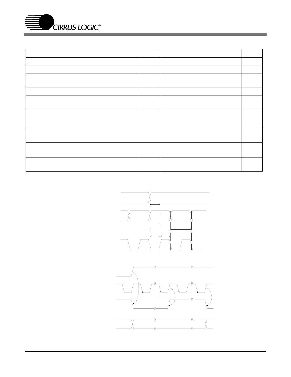
SWITCHING CHARACTERISTICS - INTERNAL SERIAL CLOCK
Notes: 6. The Duty Cycle must be 50%
+/− 1/2 MCLK Period.
7. See section 4.2.1 for derived internal frequencies.
Parameters
Symbol Min Typ
Max
Units
MCLK Frequency
1.024
-
25.6
MHz
MCLK Duty Cycle
45
-
55
%
Input Sample Rate
Single-Speed Mode
Double-Speed Mode
Fs
Fs
4
50
-
-
50
100
kHz
kHz
LRCK Duty Cycle
(Note 6)
%
SCLK Period
(Note 7)
t
sclkw
-
-
s
SCLK rising to LRCK edge
t
sclkr
-
-
s
SDATA valid to SCLK rising setup time
t
sdlrs
-
-
ns
SCLK rising to SDATA hold time
MCLK / LRCK = 512, 256 or 128
t
sdh
-
-
ns
SCLK rising to SDATA hold time
MCLK / LRCK = 384 or 192
t
sdh
-
-
ns
1
SCLK
----------------
t
sclkw
2
--------------
1
512
(
)Fs
----------------------
10
+
1
512
(
)Fs
----------------------
15
+
1
384
(
)Fs
----------------------
15
+
SDATA
*INTERNAL SCLK
LRCK
sclkw
t
sdlrs
t
sdh
t
sclkr
t
Figure 12. Internal Serial Mode Input Timing
*
The SCLK pulses shown are internal to the CS4340.
SDATA
LRCK
MCLK
*INTERNAL SCLK
1
N
2
N
Figure 13. Internal Serial Clock Generation
*
The SCLK pulses shown are internal to the CS4340. N equals MCLK divided by SCLK