Cirrus Logic CS4340 User Manual
Features, Description
1
Copyright
© Cirrus Logic, Inc. 2005
(All Rights Reserved)
www.cirrus.com
CS4340
24-Bit, 96 kHz Stereo D/A Converter for Audio
Features
!
101 dB Dynamic Range
!
-91 dB THD+N
!
+3.0 V or +5.0 V Power Supply
!
Low Clock Jitter Sensitivity
!
Filtered Line-level Outputs
!
On-chip Digital De-emphasis for 32, 44.1 and
48 kHz
!
33 mW with 3V Supply
!
Popguard
®
Technology for Control of Clicks
and Pops
!
Lead-free Packaging Available
Description
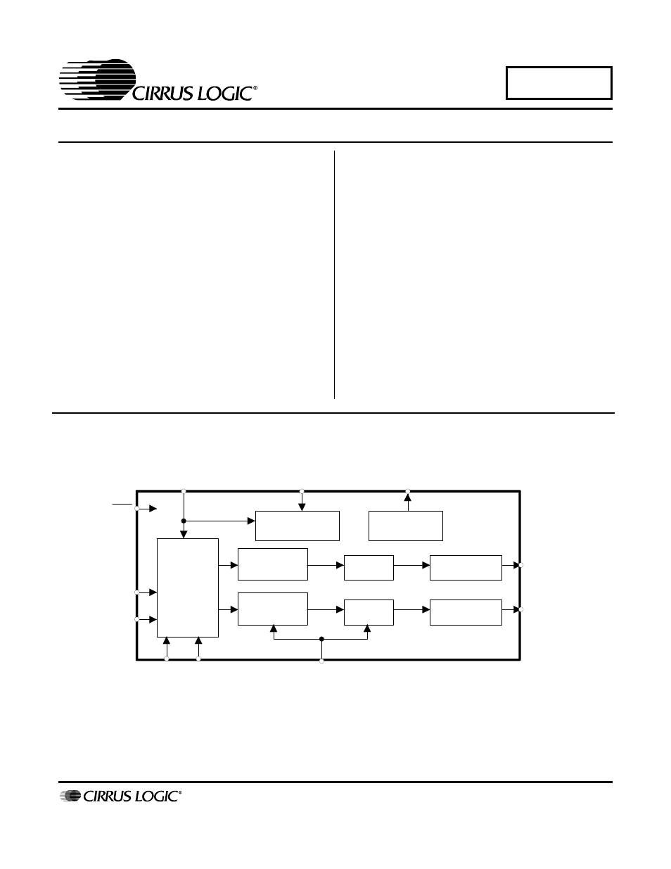
The CS4340 is a complete stereo digital-to-analog system
including digital interpolation, fourth-order delta-sigma dig-
ital-to-analog conversion, digital de-emphasis and
switched capacitor analog filtering. The advantages of this
architecture include: ideal differential linearity, no distor-
tion mechanisms due to resistor matching errors, no
linearity drift over time and temperature and a high toler-
ance to clock jitter.
The CS4340 accepts data at audio sample rates from
4 kHz to 100 kHz, consumes very little power, and oper-
ates over a wide power supply range. The features of the
CS4340 are ideal for DVD players, CD players, set-top box
and automotive systems.
ORDERING INFORMATION
CS4340-DSZ 16-pin SOIC, Lead Free,
-40 to 85 °C
CS4340-KS
16-pin SOIC
-10 to 70 °C
CS4340-KSZ 16-pin SOIC, Lead Free, -10 to 70 °C
CS4340-CZZ 16-pin TSSOP, Lead Free, -10 to 70 °C
CDB4340
Evaluation Board
I
∆Σ DAC
Analog Filter
Serial
Input
Interface
Interpolation
Filter
Analog Filter
MUTEC
AOUTL
AOUTR
RST
LRCK
SDATA
MCLK
∆Σ
External
Mute Control
SCLK/DEM1
DAC
Interpolation
Filter
De-emphasis
DEM0
DIF0 DIF1
JULY '05
DS297F3
Document Outline
- CS4340
- Features
- Description
- 1. Characteristics and Specifications
- Specified Operating Conditions
- Absolute Maximum Ratings
- Analog Characteristics (CS4340-kS/KSZ/CZZ)
- Analog Characteristics (CS4340-dsZ)
- Combined Interpolation & On-Chip Analog Filter Response
- Figure 3. Single-Speed Stopband Rejection
- Figure 4. Single-Speed Transition Band
- Figure 5. Single-Speed Transition Band (Detail)
- Figure 6. Single-Speed Passband Ripple
- Figure 7. Double-Speed Stopband Rejection
- Figure 8. Double-Speed Transition Band
- Figure 9. Double-Speed Transition Band (Detail)
- Figure 10. Double-Speed Passband Ripple
- Switching Specifications - Serial Audio Interface
- Switching Characteristics - Internal Serial Clock
- DC Electrical Characteristics
- Digital Input Characteristics
- Digital Interface Specifications
- 2. Pin Description
- 3. Typical Connection Diagram
- 4. Applications
- 5. Parameter Definitions
- 6. References
- 7. Package Dimensions
- 8. Package Thermal Resistance