Cirrus Logic CS4271 User Manual
D/a features, A/d features, System features
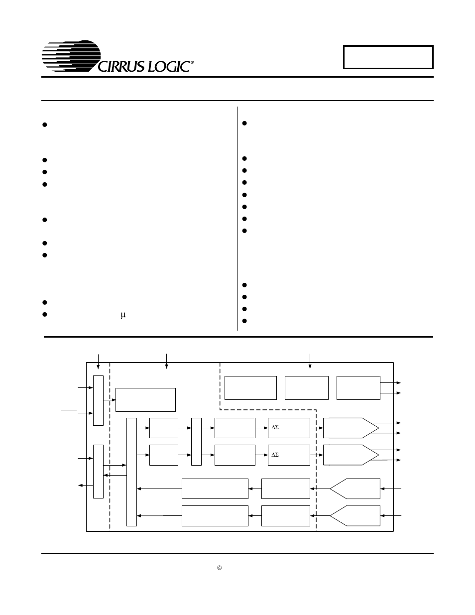
Table of contents
Document Outline
- Ordering Information
- D/A Features
- A/D Features
- System Features
- Stand-Alone Mode Feature Set
- Software Mode Feature Set
- General Description
- 1. Pin Descriptions - Software Mode
- 2. Pin Descriptions - Stand-Alone Mode
- 3. Characteristics and Specifications
- Specified Operating Conditions
- Absolute Maximum Ratings
- DAC Analog Characteristics - Commercial GRADE
- DAC Analog Characteristics - Automotive Grade
- DAC Combined Interpolation & On-Chip Analog Filter Response
- ADC Analog Characteristics - Commercial Grade
- ADC Analog Characteristics - Automotive Grade
- ADC Digital Filter Characteristics
- DC Electrical Characteristics
- Digital Characteristics
- Switching Characteristics - Serial Audio Port
- Switching Characteristics - I2C Mode Control Port
- Switching Characteristics - SPI Control Port
- 4. Typical Connection Diagram
- 5. Applications
- 5.1 Stand-Alone Mode
- 5.2 Control Port Mode
- 5.2.1 Recommended Power-Up Sequence - Access to Control Port Mode
- 5.2.2 Master / Slave Mode Selection
- 5.2.3 System Clocking
- 5.2.4 Internal Digital Loopback
- 5.2.5 Dither for 16-Bit Data
- 5.2.6 Auto-Mute
- 5.2.7 High Pass Filter and DC Offset Calibration
- 5.2.8 Interpolation Filter
- 5.2.9 De-Emphasis
- 5.2.10 Oversampling Modes
- 5.3 De-Emphasis Filter
- 5.4 Analog Connections
- 5.5 Mute Control
- 5.6 Synchronization of Multiple Devices
- 5.7 Grounding and Power Supply Decoupling
- 6. Control Port Interface
- 7. Register Quick Reference
- 8. Register Description
- 8.1 Mode Control 1 - Address 01h
- 8.2 DAC Control - Address 02h
- 8.3 DAC Volume & Mixing Control - Address 03h
- 8.4 DAC Channel A Volume Control - Address 04h
- 8.5 DAC Channel B Volume Control - Address 05h
- 8.6 ADC Control - Address 06h
- 8.7 Mode Control 2 - Address 07h
- 8.8 Chip ID - Register 08h
- 9. Parameter Definitions
- 10. Package Dimensions
- 11. Appendix
- Figure 21. DAC Single Speed (fast) Stopband Rejection
- Figure 22. DAC Single Speed (fast) Transition Band
- Figure 23. DAC Single Speed (fast) Transition Band (detail)
- Figure 24. DAC Single Speed (fast) Passband Ripple
- Figure 25. DAC Single Speed (slow) Stopband Rejection
- Figure 26. DAC Single Speed (slow) Transition Band
- Figure 27. DAC Single Speed (slow) Transition Band (detail)
- Figure 28. DAC Single Speed (slow) Passband Ripple
- Figure 29. DAC Double Speed (fast) Stopband Rejection
- Figure 30. DAC Double Speed (fast) Transition Band
- Figure 31. DAC Double Speed (fast) Transition Band (detail)
- Figure 32. DAC Double Speed (fast) Passband Ripple
- Figure 33. DAC Double Speed (slow) Stopband Rejection
- Figure 34. DAC Double Speed (slow) Transition Band
- Figure 35. DAC Double Speed (slow) Transition Band (detail)
- Figure 36. DAC Double Speed (slow) Passband Ripple
- Figure 37. DAC Quad Speed (fast) Stopband Rejection
- Figure 38. DAC Quad Speed (fast) Transition Band
- Figure 39. DAC Quad Speed (fast) Transition Band (detail)
- Figure 40. DAC Quad Speed (fast) Passband Ripple
- Figure 41. DAC Quad Speed (slow) Stopband Rejection
- Figure 42. DAC Quad Speed (slow) Transition Band
- Figure 43. DAC Quad Speed (slow) Transition Band (detail)
- Figure 44. DAC Quad Speed (slow) Passband Ripple
- Figure 45. ADC Single Speed Mode Stopband Rejection
- Figure 46. ADC Single Speed Mode Transition Band
- Figure 47. ADC Single Speed Mode Transition Band (Detail)
- Figure 48. ADC Single Speed Mode Passband Ripple
- Figure 49. ADC Double Speed Mode Stopband Rejection
- Figure 50. ADC Double Speed Mode Transition Band
- Figure 51. ADC Double Speed Mode Transition Band (Detail)
- Figure 52. ADC Double Speed Mode Passband Ripple
- Figure 53. ADC Quad Speed Mode Stopband Rejection
- Figure 54. ADC Quad Speed Mode Transition Band
- Figure 55. ADC Quad Speed Mode Transition Band (Detail)
- Figure 56. ADC Quad Speed Mode Passband Ripple
- Table 18. Revision History