Table 7. crystal frequencies, 2 clock ratio selection, Outlined in the tables 8 and – Cirrus Logic CS4271 User Manual
Page 28: Table 7, Cs4271
CS4271
28
DS592F1
To operate the CS4271 with an externally generated MCLK signal, no crystal should be used, XTI should be con-
nected to ground and XTO should be left unconnected. In this configuration, MCLK is an input and must be driven
externally with an appropriate speed clock.
5.2.3.2
Clock Ratio Selection
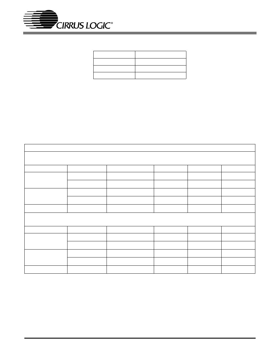
Depending on the use of an external crystal, or whether the CS4271 is in Master or Slave Mode, different
MCKL/LRCK and SCLK/LRCK ratios may be used. These ratios as well as the Control Port Register Bits that must
be set in order to obtain them are shown in Tables 8 and 9 below.
Notes: 25. For the Ratio1 and Ratio0 bits listed above, “d” indicates that any value may written.
Table 7. Crystal Frequencies
Mode
Crystal Frequency
Single Speed
512 x Fs
Double Speed
256 x Fs
Quad Speed
128 x Fs
Table 8. Clock Ratios - Control Port Mode With External Crystal
External Crystal Used, MCLK=Output
Master Mode
MCLK/LRCK
SCLK/LRCK
LRCK
Ratio1 Bit
Ratio0 Bit
Single Speed
256
64
Fs
0
512
64
Fs
1
Double Speed
128
64
Fs
0
256
64
Fs
1
Quad Speed
128
64
Fs
Slave Mode
MCLK/LRCK
SCLK/LRCK
LRCK
Ratio1 Bit
Ratio0 Bit
Single Speed
256
32, 64, 128
Fs
0
512
32, 64, 128
Fs
1
Double Speed
128
32, 64
Fs
0
256
32, 64
Fs
1
Quad Speed
128
32, 64
Fs