Cirrus Logic CDB42428 User Manual
Features, Description
1
Copyright
Cirrus Logic, Inc. 2003
(All Rights Reserved)
Cirrus Logic, Inc.
http://www.cirrus.com
CDB42428
Evaluation Board For CS424xx
Features
Single-Ended Analog Inputs and Outputs
CS8416 S/PDIF Receiver
CS5361 converters supply ADCIN1 and
ADCIN2 for CS424xx One Line Modes
CS8406 S/PDIF Digital Audio Transmitter
Header for optional external configuration of
CS424xx and board
Header for external DSP serial audio I/O
3.3 or 5.0 Volt Logic Interface supply
Demonstrates recommended layout and
grounding arrangements
Microsoft Windows® compatible software
interface to configure CS424xx and inter-
board connections
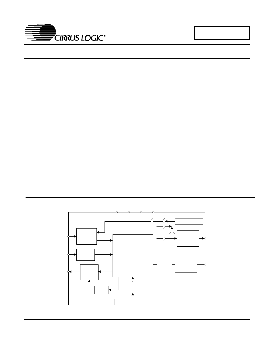
Description
The CDB42428 demonstration board is an excellent
means for evaluating the CS424xx family of highly inte-
grated multi-channel CODECs. Evaluation requires an
analog/digital signal source and analyzer, Windows®
compatible computer, and power supplies.
System timing can be provided by an on-board oscillator
or a master clock recovered from the S/PDIF input to the
CS8416. RCA phono jacks are provided for the CS5361
analog inputs and CS424xx analog inputs and outputs.
Digital data I/O is available via RCA phono jacks or opti-
cal connectors to the CS8416 and from the CS8406.
The Windows® software provides a graphical user inter-
face to make configuration of the board easy. The
software communicates through the computer’s parallel
port, and will configure the hardware to allow all features
of the CS424xx to be evaluated. The evaluation board
may also be configured to accept external timing and
data signals for operation in a user application during
system development.
ORDERING INFORMATION
CDB42428
Evaluation Board
I
PC Parallel Port
A na log Inputs
A na log Inputs
S /P D IF O utput
+18V
-18V
+5V
G N D
CPLD
Ext. Control
Analog
Filter
CS5361
(x2)
CS8406
DSP Header
S /P D IF Input
CS8416
A na log O utputs
8-ch
Analog
Output
Mute
C S 42428
Nov ‘03
DS605DB1
Document Outline
- CDB42428
- Features
- Description
- 1. System Overview
- 1.1 CS424xx
- 1.2 CS8406
- 1.3 CS8416
- 1.4 CS5361
- 1.5 Crystal Oscillator
- 1.6 Analog Input
- 1.7 Analog Outputs
- 1.8 CPLD
- 1.9 DB-25 Computer Parallel Port
- 1.10 External Control Header
- 1.11 DSP Header
- 1.12 LED Function Indicator
- 1.13 Power
- 1.14 Grounding and Power Supply Decoupling
- 1.15 External Control Header Signals
- 1.16 DSP Header Signals
- 2. Initial Board Setup
- 3. CDB425xx.EXE User's Guide
- 4. Muting Scheme
- 5. Schematics and Layout
- Figure 3. CS424xx
- Figure 4. Clocks, Data, and DSP Header
- Figure 5. SPDIF
- Figure 6. CS5361 External ADC #1
- Figure 7. CS5361 External ADC #2
- Figure 8. CS424xx Analog Inputs
- Figure 9. Analog Outputs A1 and B1
- Figure 10. Analog Outputs A2 and B2
- Figure 11. Analog Outputs A3 and B3
- Figure 12. Analog Outputs A4 and B4
- Figure 13. DB-25, Ext Ctrl Header, Reset
- Figure 14. CPLD
- Figure 15. Power
- Figure 16. CS8416
- Figure 17. Component Placement and Reference Designators
- Figure 18. Top Layer
- Figure 19. Bottom Layer
- 6. Addendum