General information, Schematic description, 1 block diagram – Cirrus Logic CRD4205-2 User Manual
Page 3: 2 analog inputs, Table 1. microphone input jumper jp1, 3 analog output
CRD4205-2
DS489RD2A1 3
1. GENERAL INFORMATION
The CRD4205-2 is designed to emulate a high
quality PC audio docking station. This is not a
stand-alone card but used in conjunction with the
CRD4205-1. The CRD4205-1 contains a CS4205
audio codec and simulates the audio sub-system in
a PC notebook computer.
The CRD4205-2 has all the circuitry typically
found in a high quality PC digital docking audio
sub-system. In addition, this reference design in-
cludes four channel analog audio outputs driven by
24-bit serial DACs. Microphone, stereo Line, and
stereo CD inputs feature high quality serial 18-bit
ADCs.
2. SCHEMATIC DESCRIPTION
This section describes the CRD4205-2 schematics
shown in figures 1 through 4. These schematics are
also available in the CMK4205-3 manufacturing
kit as ORCAD 7.2 files.
2.1 Block Diagram
The block diagram in Figure 1, shows the intercon-
nection between schematic pages. The schematic is
divided into three blocks: Analog In, Analog Out,
and PCI Bus.
2.2 Analog Inputs
The Analog Input page in Figure 2 illustrates the
Mic, stereo Line and stereo CD inputs and their as-
sociated ADCs. The LINE inputs connect to a di-
vider circuit that reduces the voltage by 6 dB to
allow for line level sources up to 2 Vrms. The
100 pF capacitors are provided on Line In and Mic
In for EMI suppression. These may be removed if
EMC testing determines they are not required.
Since the analog inputs of the CS5331 ADCs are
DC biased, all of the analog inputs must be AC cou-
pled. The microphone input is coupled with a
0.1
µ
F capacitor. The Line and CD inputs are AC
coupled with 2.2 µF capacitors to minimize the
low frequency roll-off.
The analog audio input signals are converted to
digital data by three CS5331A 18-bit ADCs. The
ADCs share a common clock, but have indepen-
dent data outputs. The clock and serial data signals
are routed to the docking port header.
The MIC IN circuit complies with PC-99 require-
ments for microphone phantom power and recom-
mendations for frequency response roll-off. The
3 dB roll-off frequencies are 60 Hz and 15 kHz.
Phantom power for the microphones is derived
from the +5 V analog supply and filtered by R11,
C13, and R12.
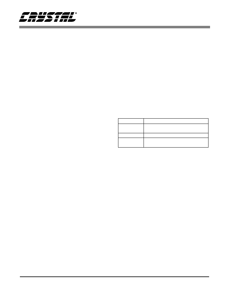
Jumper JP1 controls how the microphone signal is
routed to the ADC, U3.
2.3 Analog Output
The CS4205 sends audio to the docking port
through I
2
S serial digital outputs, as shown in
figure 3. These signals are converted to analog au-
dio through two CS4334 serial DACs. Both
CS4334s share common clocks but have indepen-
dent data inputs. All clocks originate from the
CS4205 on the CRD4205-1 card.
The output of the DACs are connected to a Motor-
ola MC34072 dual op-amp which is capable of
driving high impedance (10 k
Ω
or higher) line lev-
el signals. This circuit has a gain of 3 dB.
It is possible to drive headphones with impedances
as low as 32
Ω
by replacing the MC34072 with a
TDA1308 and increasing the values of C23, C24,
C29, and C30 to 220
µ
F. These op-amps are pin
compatable.
JP1 Position Description
Out Microphone signal routed to AINL of
the CS5331A. The AINR is floating.
1-2 Not Used!
2-3 Microphone signal routed to both
AINL and AINR of the CS5331A.
Table 1. Microphone Input Jumper JP1