4 power-up and power-down, 1 recommended power-up sequence, Cs35l00 – Cirrus Logic CS35L00 User Manual
Page 19: 1 zero crossing on power-up functionality, And t
CS35L00
DS906PP1
19
Static signals (i.e. sine waves at a fixed amplitude) are easier to consider than are dynamic signals (i.e.
musical content), as they are governed by the same equation as that listed in
and
. Modifications to that equation are limited to the voltage term (V) and the frequency
term (f), depending on whether the static input signal amplitude is causing the output devices to switch at
76 kHz or 192 kHz, and to operate off of the VBATT supply or off of the internally generated LDO.
It is important to note that the HD and FHD modes offer significant improvement over traditional Class D
in idle power dissipation when an external output filter is necessary. This is because the voltage term (V)
is significantly reduced in HD and FHD mode. As can be seen in the equation, this is notable because
reduction in the operating voltage reduces power losses not linearly, but instead exponentially- due to the
voltage squared term (V
2
). It is also notable that when operated at high output levels, FHD modes also
offers unique improvement in output filter losses, due to reducing the switching frequency (f) at higher out-
put levels.
5.4
Power-Up and Power-Down
When pulled to a logic low state, the SD pin tristates the outputs and shuts down the CS35L00 device, put-
ting it into a low power mode.
5.4.1
Recommended Power-Up Sequence
1. With the SD pin pulled low, apply power to the CS35L00 and wait for the power supply to be stable.
2. Set the SD pin high to begin normal operation.
5.4.1.1
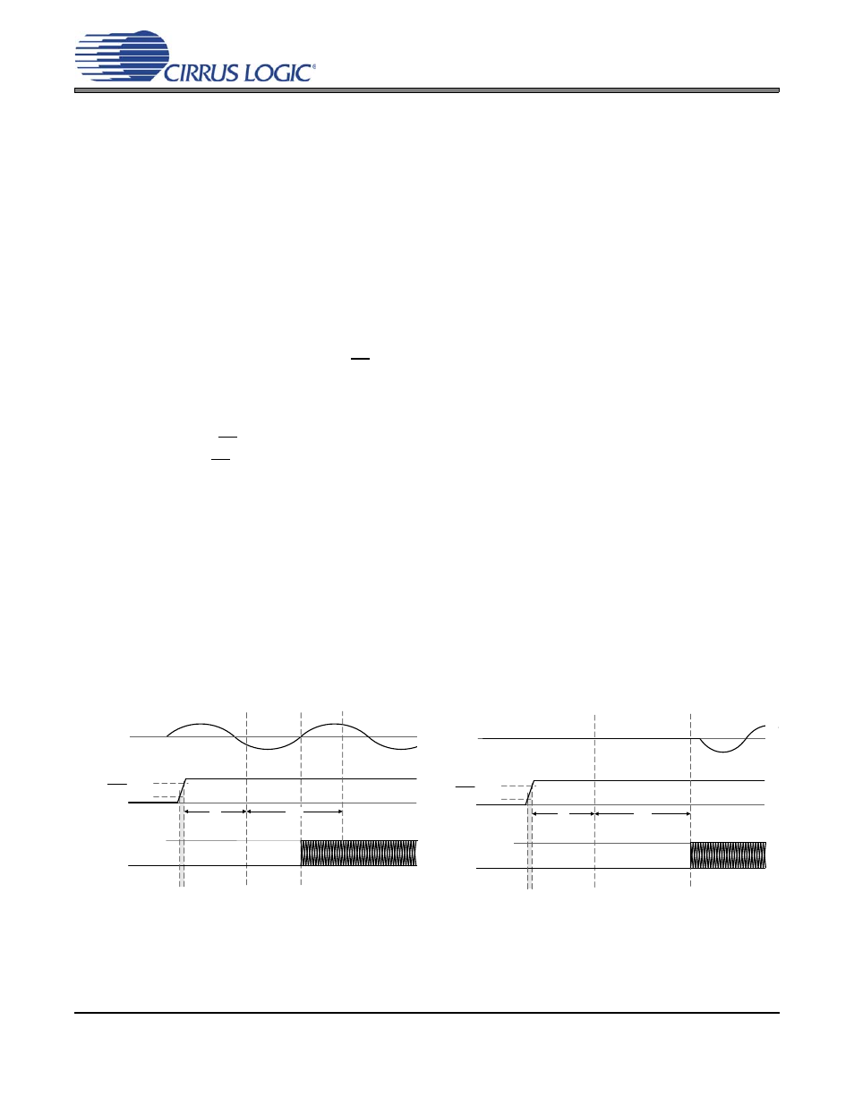
Zero Crossing on Power-Up Functionality
The CS35L00 implements an input-signal zero-crossing detection function that is enabled during power-
up. This function is designed to prevent audible artifacts and eliminate any need to mute the amplifier’s
input audio signal during the power-up process.
After a minimum start-up time of t
start
, the CS35L00 will begin to detect input-signal zero-crossings. The
amplifier will then enable its switching outputs at the time of the first detected input-signal zero-crossing
transition. If no input-signal zero-crossing is detected before t
timeout
, the zero-crossing function will time-
out and the outputs will begin switching immediately.
Both t
start
and t
timeout
“Power-Up & Power-Down Characteristics” on page 14
OUT+/-
Shut-Down /
Low Power
Mode
t
start
SD
V
IH
Device Ready:
Waiting for Zero
Crossing Input
Signal or t
timeout
Internal
Start-Up
V
IL
PWM OUT+/-
Active
VBATT or VLDO
IN+/-
t
timeout
Figure 6. Power-Up Timing with Input
Zero-Crossing
Figure 7. Power Up Timing without Input
Zero-Crossing
OUT+/-
Shut-Down /
Low Power
Mode
t
start
SD
V
IH
Device Ready: Waiting for Zero
Crossing Input Signal or t
timeout
Internal
Start-Up
V
IL
PWM OUT+/-
Active
VBATT or VLDO
IN+/-
t
timeout