Cirrus Logic CS3318 User Manual
Cs3318, Channel analog volume control, Features
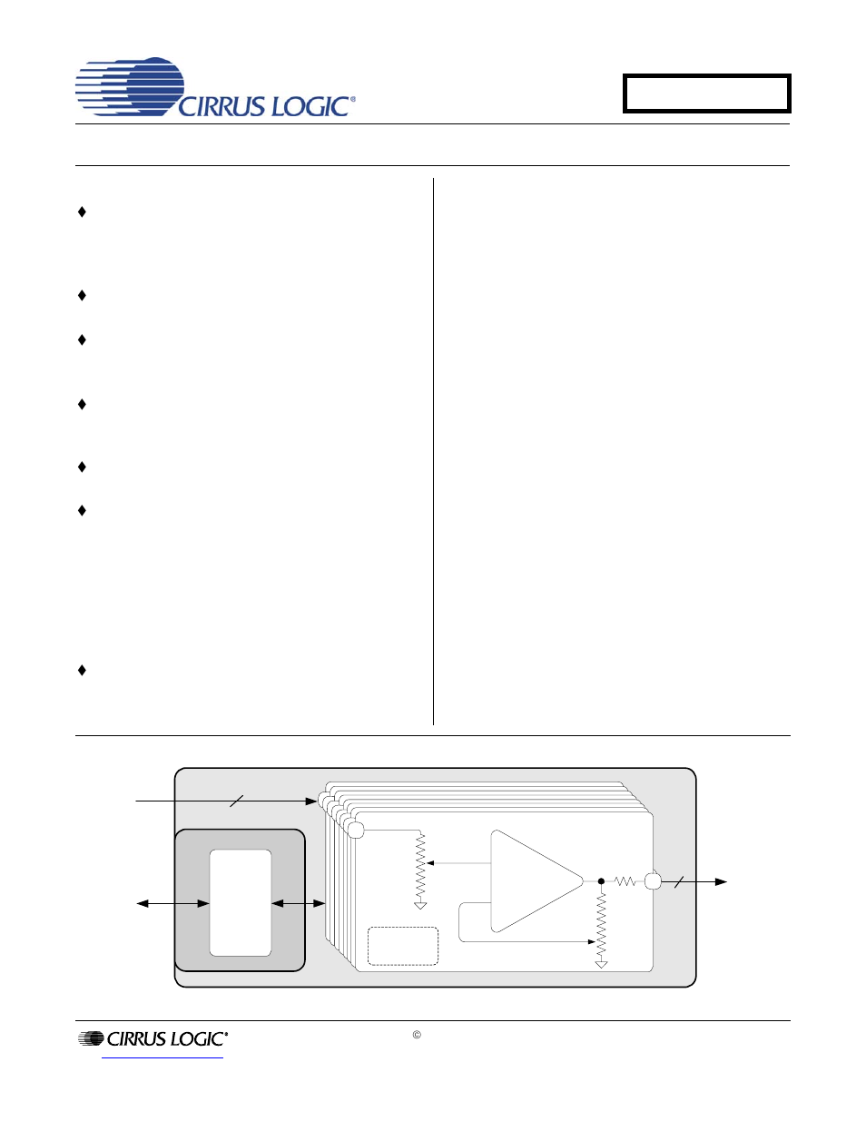
Table of contents
Document Outline
- 1. Pin Descriptions
- 2. Characteristics and Specifications
- 3. Typical Connection Diagram
- 4. Detailed Block Diagram
- 5. Applications
- 5.1 General Description
- 5.2 System Design
- 5.3 Power-Up and Power-Down
- 5.4 Volume & Muting Control Architecture
- 5.5 Volume Controls
- 5.6 Muting Controls
- 5.7 Zero-Crossing Detection
- 5.8 System Serial Control Configuration
- 5.9 I·C/SPI Serial Control Formats
- 6. CS3318 Register Quick Reference
- 7. CS3318 Register Descriptions
- 7.1 Ch 1-8 Volume - Addresses 01h - 08h
- 7.2 ¹dB Control - Address 09h
- 7.3 Mute Control - Address 0Ah
- 7.4 Device Configuration 1 - Address 0Bh (Bit 5)
- 7.5 Device Configuration 2 - Address 0Ch
- 7.6 Channel Power - Address 0Dh
- 7.7 Master Power - Address 0Eh
- 7.8 Freeze Control - Address 0Fh
- 7.9 Master1 Mask - Address 10h
- 7.10 Master1 Volume - Address 11h
- 7.11 Master1 Control - Address 12h
- 7.12 Master2 Mask - Address 13h
- 7.13 Master2 Volume - Address 14h
- 7.14 Master2 Control - Address 15h
- 7.15 Master3 Mask - Address 16h
- 7.16 Master3 Volume - Address 17h
- 7.17 Master3 Control - Address 18h
- 7.18 Group2 Chip Address 19h
- 7.19 Group1 Chip Address 1Ah
- 7.20 Individual Chip Address 1Bh
- 7.21 Chip ID - Address 1Ch
- 8. Parameter Definitions
- 9. Package Dimensions
- 10. Thermal Characteristics and Specifications
- 11. Ordering Information
- 12. Revision History