5 pll clock output, Figure 14. pll clock output options, 6 auxiliary output – Cirrus Logic CS2000-OTP User Manual
Page 18: Figure 15. auxiliary output selection, 5 pll clock output 5.6 auxiliary output, Cs2000-otp
CS2000-OTP
18
DS758F2
5.5
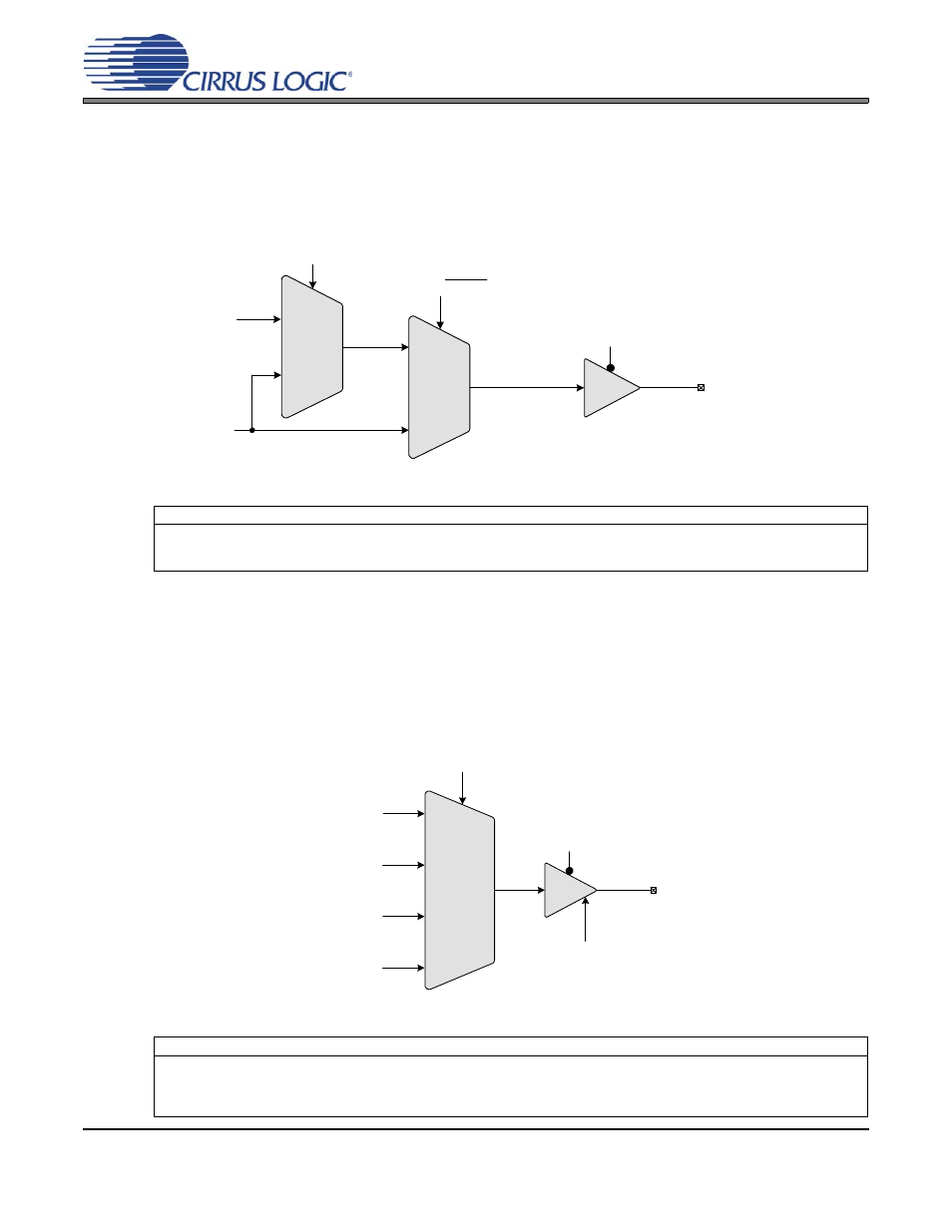
PLL Clock Output
The PLL clock output pin (CLK_OUT) provides a buffered version of the output of the frequency synthesizer.
The driver can be set to high-impedance with the M2 pin when the M2Config[1:0] global parameter is set to
either 000 or 010. The output from the PLL automatically drives a static low condition while the PLL is un-
locked (when the clock may be unreliable). This feature can be disabled by setting the ClkOutUnl global
parameter, however the state CLK_OUT may then be unreliable during an unlock condition.
Figure 14. PLL Clock Output Options
5.6
Auxiliary Output
The auxiliary output pin (AUX_OUT) can be mapped, as shown in
, to one of four signals: refer-
ence clock (RefClk), input clock (CLK_IN), additional PLL clock output (CLK_OUT), or a PLL lock indicator
(Lock). The mux is controlled via the AuxOutSrc[1:0] modal parameter. If AUX_OUT is set to Lock, the Aux-
LockCfg global parameter is then used to control the output driver type and polarity of the LOCK signal (see
). If AUX_OUT is set to CLK_OUT, the phase of the PLL Clock Output signal on
AUX_OUT may differ from the CLK_OUT pin. The driver for the pin can be set to high-impedance using the
M2 pin when the M2Config[1:0] global parameter is set to either 001 or 010.
Figure 15. Auxiliary Output Selection
Referenced Control
Parameter Definition
ClkOutUnl..............................
“Enable PLL Clock Output on Unlock (ClkOutUnl)” on page 24
ClkOutDis ..............................
“M2 Configured as Output Disable” on page 19
M2Config[2:0]........................
“M2 Pin Configuration (M2Config[2:0])” on page 25
Referenced Control
Parameter Definition
AuxOutSrc[1:0]......................
“Auxiliary Output Source Selection (AuxOutSrc[1:0])” on page 23
AuxOutDis .............................
“M2 Configured as Output Disable” on page 19
AuxLockCfg...........................
“AUX PLL Lock Output Configuration (AuxLockCfg)” section on page 24
M2Config[2:0]........................
“M2 Pin Configuration (M2Config[2:0])” on page 25
PLL Locked/Unlocked
PLL Output
2:1 Mux
M2 pin with
M2Config[1:0] = 000, 010
2:1 Mux
ClkOutUnl
0
PLL Clock Output Pin
(CLK_OUT)
0
1
0
1
PLL Clock Output
PLLClkOut
Frequency Reference Clock
(CLK_IN)
PLL Lock/Unlock Indication
(Lock)
Timing Reference Clock
(RefClk)
PLL Clock Output
(PLLClkOut)
4:1 Mux
Auxiliary Output Pin
(AUX_OUT)
AuxOutSrc[1:0]
AuxLockCfg
M2 pin with
M2Config[1:0] = 001, 010