General description, 1 overview, 2 ic startup – Cirrus Logic CS1616A User Manual
Page 8: 3 ic operation, 1 dimmer detection
CS1615A/16A
8
DS1033PP2
5. GENERAL DESCRIPTION
5.1 Overview
The CS1615A and CS1616A are high-performance single stage
dimmable offline AC/DC controllers. The CS1615A/16A is a
cost-effective solution that provides unmatched single- and
multi-lamp dimmer-compatibility performance for dimmable LED
applications. The CS1615A is designed for 120VAC line voltage
applications, and the CS1616A is designed for 230VAC line
voltage applications.
Across a broad range of dimmers, the CS1615A/16A provides
smooth flicker free dimming, and consistently dims to nearly zero
light output, which closely matches the dimming performance of
incandescent light bulbs. Cirrus Logic’s patent pending approach
to dimmer compatibility provides full functionality on a wide range
of dimmers, including leading-edge, trailing-edge, and digital
dimmers.
5.2 IC Startup
A high-voltage source-follower circuit is used to deliver startup
current to the IC. During steady-state operation, an auxiliary
winding on the transformer/inductor biases this circuit to an off
state to improve system efficiency, and all IC supply current is
provided from the auxiliary winding. The patent-pending
technology of the high-voltage source-follower circuit enables
system compatibility with digital dimmers (dimmers containing an
internal power supply) by providing a continuous path for the
dimmer’s power supply to recharge during its off state. During
steady-state operation, high-voltage FET Q2 in this circuit is
source-controlled by a variable internal current source on the
SOURCE pin to create the dimmer-compatibility circuit.
A resistor is connected between the SOURCE pin and the source
of source-follower FET. Resistor R5 is designed to control the
startup in-rush current into the SOURCE pin of the IC, which
allows for diode D3 to be specified as a standard low-cost diode.
During initial power-up, the IC executes a fast startup algorithm,
which drives the converter with peak currents that are above
normal to charge the output capacitor. Once the output capacitor
reaches a defined voltage, the IC drives the converter with
nominal peak currents until normal operation is achieved.
5.3 IC Operation
5.3.1 Dimmer Detection
The CS1615A/16A dimmer switch detection algorithm
determines if a non-dimming switch, a leading-edge dimmer
switch, or a trailing-edge dimmer switch controls the solid-state
lighting (SSL) system. For each type of switch, the IC uses a
different operating mode: for a non-dimming switch, No-dimmer
Mode is used; for a leading-edge dimmer switch, Leading-edge
Mode is used; for a trailing-edge dimmer switch, Trailing-edge
Mode is used. As a result, the overall performance is optimized
in terms of power losses, efficiency, power factor, THD, and
dimmer compatibility.
When the IC completes UVLO, it executes in Leading-edge
Mode until the dimmer switch detection algorithm determines the
appropriate operating mode for the IC. The dimmer switch
detection algorithm uses the input line voltage slope and dimmer
phase angle to determine the operating mode that matches the
type of dimmer switch in the system. From there on, it periodically
learns the dimmer type and can change the operating mode if the
type of dimmer switch changes.
5.3.1.1 No-dimmer Mode
If the CS1615A/16A determines that the line is not phase cut by
a dimmer switch, the IC operates the flyback/buck-boost in PFC
mode to achieve a power factor greater than 0.9 while regulating
the load current to a level set by resistor R
CTRL2
. In addition, a
No-dimmer Mode algorithm is applied to the source-controlled
dimmer-compatibility circuit for optimal performance, including
less than 20% of THD and highest possible overall efficiency.
5.3.1.2 Leading-edge Mode
If the CS1615A/16A determines that the line is phase cut by a
leading-edge dimmer switch, the IC operates the flyback/buck-
boost in Dimmer Mode and the IC sets the dimmer firing current
as well as the attach current using a source-controlled dimmer-
compatibility circuit for stable TRIAC dimmer operation.
5.3.1.3 Trailing-edge Mode
If the CS1615A/16A determines that the line is phase cut by a
trailing-edge dimmer switch, the IC operates the flyback/buck-
boost in Dimmer Mode. The IC charges the capacitor in the
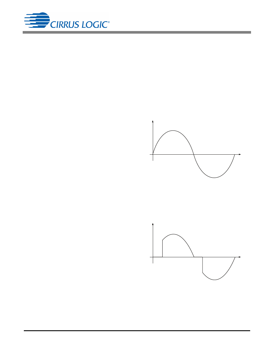
Figure 9. No-dimmer Mode Waveform
Figure 10. Leading-edge Mode Phase-cut Waveform